Configuring Virtual Edge
This chapter describes how to configure Virtual Edge after deploying it on Hyper-V. It includes the following sections:
Completing the configuration checklist
This table lists the parameters you specify to complete the initial configuration of the Edge appliance. Be prepared to provide values for these parameters.
Appliance | Parameter | Your value |
SteelFusion Edge (the Primary Interface) | Hostname | |
IP address | |
Netmask | |
Default gateway (the WAN gateway) | |
DNS IP address | |
Domain name for the appliance | |
Administrator password | |
SMTP server IP address | |
Events and failures notification email address | |
Primary interface speed | |
Primary interface duplex | |
In-Path Deployments | In-path interface IP address | |
In-path netmask | |
In-path gateway | |
In-path: LAN interface speed | |
In-path: LAN interface duplex | |
In-path: WAN interface speed | |
In-path: WAN interface duplex | |
Running the configuration wizard
Connect to the Virtual Edge VM and perform the initial configurations.
To perform initial configurations on the Virtual Edge VM
1. Open Hyper-V Manager and power on Riverbed Virtual SteelFusion Edge VM.
2. Connect to the Virtual Edge VM console.
3. Log in as administrator user (admin) and enter the default password (password). For example:
login as: admin
Sent username "admin"
password: password
The configuration wizard automatically starts after you have entered the login and default password. After you have established a connection, you configure the Edge appliance using the configuration wizard.
4. If you have a SteelCentral Controller for SteelHead (SCC) appliance installed in your network to manage multiple Edge appliances, you can use it to automatically configure them:
Do you want to auto-configure using a SCC? no
If you enter yes, you are prompted for the SCC hostname or IP address. The hostname or IP address is used to contact the SCC. The default value is riverbedcmc. If you enter no, the wizard continues.
Note: If you mistakenly enter
yes, to return to the wizard from the CLI, enter the
configuration jump-start command from configuration mode. For more information, see
To restart the configuration wizard.
5. To start the configuration wizard, type yes at the system prompt and press Enter.
Do you want to use the configuration wizard for initial configuration? yes
Note: Press ? for help; press Ctrl+B to go back to the previous step.
6. Complete the configuration wizard steps on the branch office Edge appliance as described in this table.
Wizard prompt | Description | Example |
Step 1: Hostname? | Enter the hostname for the Edge appliance. | Hostname? amnesiac |
Step 2: Use DHCP on the primary interface? | You are given the option to enable the DHCP to automatically assign an IP address to the primary interface for the Edge appliance. We recommend that you do not set DHCP. The default value is yes. | Use DHCP on the primary interface? no |
Step 3: Primary IP address? | Enter the IP address for the Edge appliance. | Primary IP address? 10.10.10.6 |
Step 4: Netmask? | Enter the netmask address. | Netmask? 255.255.0.0 |
Step 5: Default gateway? | Enter the default gateway for the Edge appliance. | Default gateway? 10.0.0.1 |
Step 6: Primary DNS server? | Enter the primary DNS server IP address. | Primary DNS server? 10.0.0.2 |
Step 7: Domain name? | Enter the domain name for the network where the Edge appliance is to reside. If you set a domain name, you can enter hostnames in the system without the domain name. | Domain name? example.com |
Step 8: Admin password? | We strongly recommend that you change the default administrator password at this time. The password must be a minimum of six characters. The default administrator password is password. | Admin password? xxxyyy |
Step 9: SMTP server? | Enter the name of the SMTP server. External DNS and external access for SMTP traffic is required for email notification of events and failures to function. Note: Make sure that you provide a valid SMTP server to ensure that the email notifications for events and failures are sent to the correct destinations. | SMTP server? natoma |
Step 10: Notification email address? | Enter a valid email address to which notification of events and failures are to be sent. | Notification email address? example@xample.com |
Step 11: Set the primary interface speed? | Enter the speed on the primary interface (that is, the Edge appliance). Make sure that this value matches the setting on your router or switch. The default value is auto. | Set the primary interface speed? [auto] auto |
Step 12: Set the primary interface duplex? | Enter the duplex mode on the primary interface. Make sure that this value matches the setting on your router or switch. The default value is auto. | Set the primary interface duplex? [auto] auto |
Step 13: Would you like to activate the in-path configuration? | Enter yes at the system prompt to configure in-path support. An in-path configuration is a configuration in which the Edge appliance is in the direct path of the client and server. | Would you like to activate the in-path configuration? yes |
Step 14: In-Path IP address? | Enter the in-path IP address for the Edge appliance. | In-Path IP address? 10.11.11.6 |
Step 15: In-Path Netmask? | Enter the in-path netmask address. | In-Path Netmask? 255.255.0.0 |
Step 16: In-Path Default gateway? | Enter the in-path default gateway (the WAN gateway). | In-Path Default gateway? 10.11.11.16 |
Step 17: Set the in-path: LAN interface speed? | Enter the in-path, LAN interface speed. Make sure that this value matches the setting on your router or switch. The default value is auto. | Set the in-path: LAN interface speed? [auto] auto |
Step 18: Set the f: LAN interface duplex? | Enter the in-path, LAN duplex value. Make sure that this value matches the setting on your router or switch. The default value is auto. | Set the in-path: LAN interface duplex? [auto] auto |
Step 19: Set the in-path: WAN interface speed? | Enter the in-path, WAN interface speed. Make sure that this value matches the setting on your router or switch. The default value is auto. | Set the in-path: WAN interface speed? [auto] auto |
Step 20: Set the in-path: WAN interface duplex? | Enter the in-path, WAN duplex speed. Make sure that this value matches the setting on your router or switch. The default value is auto. | Set the in-path: WAN interface duplex? [auto] auto |
The system confirms your settings.
You have entered the following information:
1. Hostname: amnesiac
2. Use DHCP on primary interface: no
3. Primary IP address: 10.10.10.6
4. Netmask: 255.255.0.0
5. Default gateway: 10.0.0.1
6. Primary DNS server: 10.0.0.2
7. Domain name: example.com
8. Admin password: xxxyyy
9. SMTP server: natoma
10. Notification email address: example@example.com
11. Set the primary interface speed: auto
12. Set the primary interface duplex: auto
13. Would you like to activate the in-path configuration: yes
14. In-Path IP address: 10.11.11.6
15. In-Path Netmask: 255.255.0.0
16. In-Path Default gateway: 10.11.11.16
17. Set the in-path:LAN interface speed: auto
18. Set the in-path:LAN interface duplex: auto
19. Set the in-path:WAN interface speed: auto
20. Set the in-path:WAN interface duplex: auto
To change an answer, enter the step number to return to.
Otherwise hit <enter> to save changes and exit.
Choice:
The Edge appliance configuration wizard automatically saves your configuration settings.
7. To log out of the system, enter the exit command at the system prompt:
amnesiac> exit
To restart the configuration wizard
• Enter the following commands at the system prompt:
> enable
# configure terminal
(config) # configuration jump-start
For more information about the CLI, see the Riverbed Command-Line Interface Reference Manual.
Verifying connection to the Virtual Edge
Perform this task to verify that you have properly connected the Virtual Edge.
To verify you are connected to the appliance
1. Verify that you can connect to the CLI using a computer with a Secure Shell (SSH) client that is connected to the Edge VM’s primary port.
2. At the system prompt, enter one of the following commands:
ssh admin@<host>.<domain>
or
ssh admin@<ip-address>
3. You are prompted for the administrator password. This is the password you set in the configuration wizard.
4. At the system prompt, ping from the management interface:
ping -I <primary-ip-address> <primary-default-gateway>
5. At the system prompt, ping from the in-path default gateway:
ping -I <in-path-ip-address> <in-path-default-gateway>
6. Run the show interface command to confirm whether traffic status is Normal, Bypass, or Disconnect.
If you have problems connecting to the Virtual Edge, see the “Troubleshooting” chapter of the SteelHead Installation and Configuration Guide on the Riverbed Support website.
Connecting to the Management Console
After you configure the Edge appliance, you can check and modify your configuration settings and view performance reports and system logs in the Management Console. You can connect to the Management Console through any supported web browser.
To connect to the Management Console, you must know the host, domain, and administrator password that you assigned in the configuration wizard.
Before you begin
• Cookies and JavaScript must be enabled in your web browser.
• Before you begin, clear your browser cache and cookies to ensure the user interface displays correctly.
To connect to the Management Console
1. Specify the URL for the Management Console in the location box of your web browser:
<protocol>://<host>.<domain>
The <protocol> variable is http or https. HTTPS uses the Secure Socket Layer (SSL) protocol to ensure a secure environment. When you connect using HTTPS, the system prompts you to inspect and verify the SSL certificate. This is a self-signed certificate that provides encrypted web connections to the Management Console. The system re-creates the certificate when you change the appliance hostname or when the certificate expires.
The secure vault does not protect the self-signed certificate used with HTTPS connections.
The <host> variable is the hostname you assigned to the Edge appliance primary interface in the configuration wizard. If your DNS server maps that IP address to a name, you can specify the DNS name.
The <domain> variable is the full domain name for the appliance.
Note: Alternatively, you can specify the IP address instead of the host and domain name.
The Management Console appears, displaying the login page.
Figure: Login page
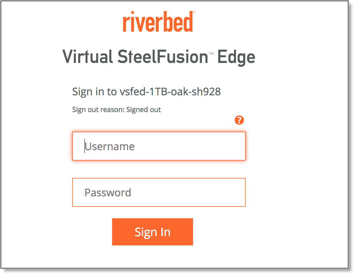
2. In the Username text box, specify the user login: admin, monitor, a login from a RADIUS or TACACS+ database, or any local accounts created using the Role-Based Accounts feature. The default login is admin.
Users with administrator (admin) privileges can configure and administer the Edge. Users with monitor privileges can view the Edge reports and user logs and change their own password. A monitor user cannot make configuration changes.
3. In the Password text box, type the password you assigned in the configuration wizard of the Edge appliance. (The default administrator password for the Edge is password.)
4. Click Sign In to display the Dashboard.
Verifying WAN optimization
Perform this task to verify that you have properly configured the Edge appliance.
To verify optimization
1. Choose Optimization > Reports: Bandwidth Optimization in the Management Console to verify optimization.
2. Map a remote drive on a client machine.
3. Drag and drop a 1-MB file from the client to the remote server. Ensure that the server is located across the WAN.
4. Drag and drop the 1-MB file again. Performance improves significantly.
Checking for speed and duplex errors
If you selected autonegotiation (auto) for your in-path and primary interfaces, you must ensure that the Edge appliance negotiated the speed and duplex at the rate your devices expect. For example, ensure settings are auto on the LAN and WAN and 100 FULL on the LAN and WAN. You can verify your speed and duplex settings in the Configure > Networking: Inpath0_0 page and the Networking > Networking: Base Interfaces page of the Management Console.
To check for speed and duplex errors
1. In the Management Console, choose Administration > Diagnostics: System Logs.
2. Check the system logs for duplex or speed errors.
3. Choose Networking > Reports: Current Connections page.
4. Check for duplex and speed errors.
If you find errors, change the speed and duplex settings on your LAN and WAN interface in the Configure > Networking: Inpath 0_0 page.
Enabling communication with host hypervisor
You can monitor host hypervisor version, connectivity, and system resources (CPU and memory) allocated to the Virtual Edge VM on Hyper-V. Virtual Edge communicates with Hyper-V through the Windows Remote Management (WinRM) protocol. WinRM is enabled during Virtual Edge installation. Do not disable WinRM.
Host hypervisor credentials
To enable communication between Virtual Edge and Hyper-V, add the host hypervisor credential details such as hostname, username, and password in Virtual Edge.
To add host hypervisor credentials
1. In the Management Console, choose Administration > Host Hypervisor: Configuration to display the Host Credentials page.
Figure: Host Credentials page
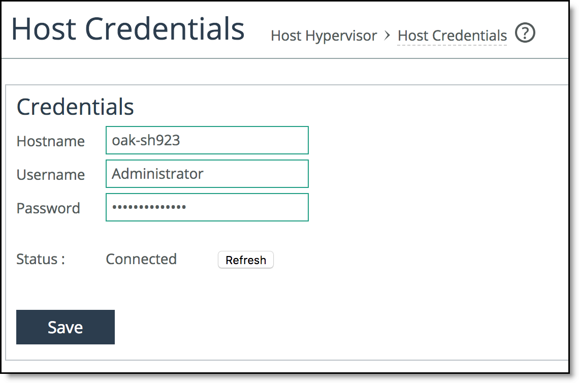
2. Specify the hostname of the host hypervisor.
3. Specify the username and password.
4. Click Save to save the host hypervisor details.
The host hypervisor connectivity status is displayed in the Credentials pane.
5. Optional: Click Refresh to refresh the information obtained from the host hypervisor.
Host hypervisor alarms
Host hypervisor alarms are raised during system errors and high usage of resources. To view and monitor the alarms, add the hypervisor details and enable communication between Virtual Edge and Hyper-V. You can set the alarms in the Administration > System Settings: Alarms page. Enabling alarms is optional. For more information about enabling the alarms, see the SteelFusion Edge User Guide.
To view and monitor host hypervisor alarms
• In the Management Console, choose Administration > Host Hypervisor: Alarms to display the Alarms page.
The hypervisor alarms are listed in the Alarms page with their corresponding status. You can also choose Administration > Diagnostics: Alarm Status to display the Alarms page and view these alarms under the Host Hypervisor section.
Figure: Alarms page
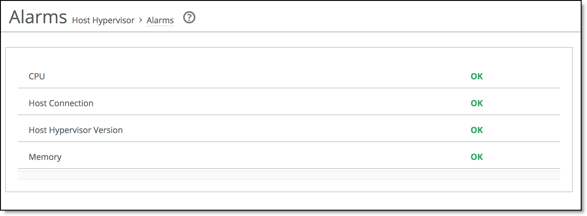
The table summarizes the alarms displayed in the Alarms page.
Control | Description |
CPU | Indicates whether or not the CPU capacity and cores reserved for the Virtual Edge VM hosted on Hyper-V are sufficient to support Virtual Edge operations. |
Host Connection | Indicates whether or not the connectivity to the host Hyper-V is established with the Virtual Edge VM. The reason for connection failure is specified in the alarm description. |
Host Hypervisor Version | Indicates whether or not the host hypervisor is running an OS version that is supported by Virtual Edge. |
Memory | Indicates whether or not the memory reserved for the Virtual Edge VM hosted on Hyper-V is sufficient to support Virtual Edge operations. The alarm is also raised if the memory allocation is dynamic. |
System Dumps
You can generate, display, and download system dumps in the System Dumps page. A system dump contains a copy of the kernel data on the system. System dump files can help you diagnose problems in the system. To access the System Dumps page, in the Management Console, choose Administration > Diagnostics: System Dumps.
Figure: System Dumps page
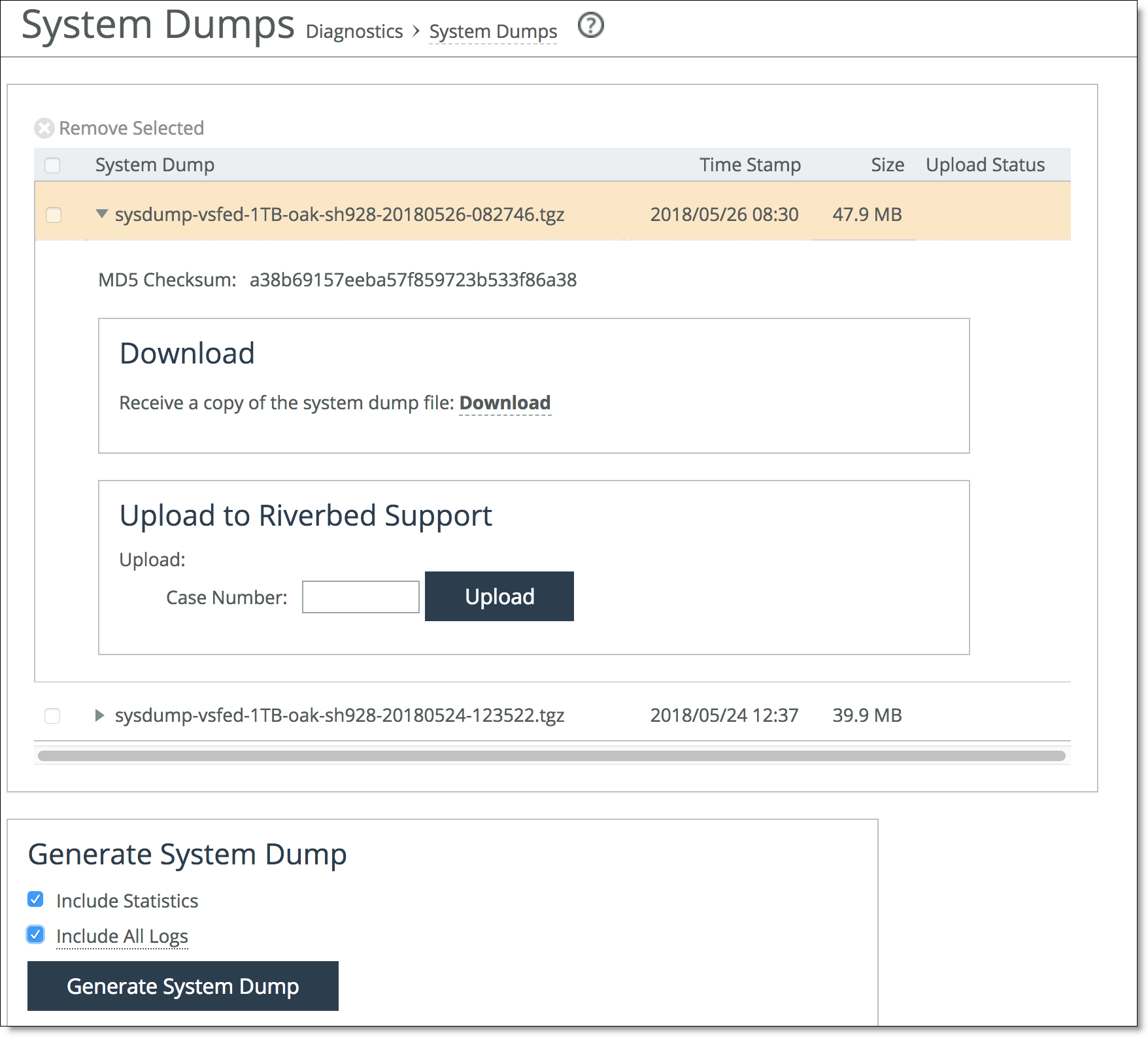
You need to enable the host hypervisor channel to allow collection of host logs. For more information about enabling the host hypervisor channel, see
Enabling communication with host hypervisor. You can identify the host log files at the $(systemdrive)\rvbd_logs location in the system drive with the naming format rvbd_sf_virtual_edge_<timestamp>_log.zip. The installer logs are available at the $<install_location>\logs location. Where, <install_location> is the installation path specified during Virtual Edge installation.
For more information about how to generate, view, and share system dumps with Riverbed support, see the SteelFusion Edge User Guide.
Mapping a LUN from a storage array to the Edge
You can expose LUNs by scanning for LUNs on the storage array, and then mapping them to the Edge. After exposing LUNs, you can further configure them for failover, MPIO, snapshots, and pinning and prepopulation.
In the Core Management Console, you can expose and configure LUNs by choosing Configure > Manage: LUNs. For more information, see the SteelFusion Core User Guide.
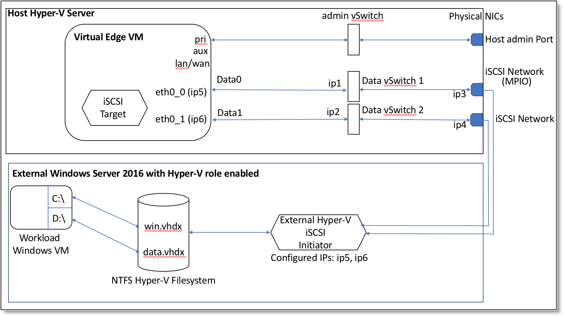
Provisioning Virtual Edge storage to an external Windows server
You can provision Virtual Edge storage to an external Windows server. For more information, see
the Solution Guide - Deploying a Windows Branch Office with SteelFusion on the Riverbed Community site at
https://community.riverbed.com/helpcenter/s/article/DOC-4671. For information about Windows persistent bindings for mounted iSCSI LUNs, see the
SteelFusion Design Guide.
Figure: Provisioning Virtual Edge storage to an external Windows server
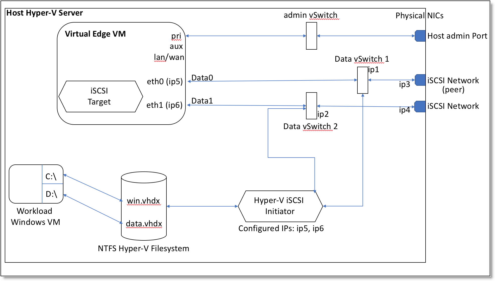
Provisioning Virtual Edge storage to a local host
Virtual Edge is installed on the iSCSI initiator of the host Windows server. You can configure the iSCSI initiator to communicate to the iSCSI target presented by the Virtual Edge. For more information, see
the Solution Guide - Deploying a Windows Branch Office with SteelFusion on the Riverbed Community site at
https://community.riverbed.com/helpcenter/s/article/DOC-4671. For information about Windows persistent bindings for mounted iSCSI LUNs, see the
SteelFusion Design Guide.
Figure: Provisioning Virtual Edge storage to a local host
Verifying and installing Hyper-V Integration Services on VMs
Hyper-V Integration Services provides communication between the guest VMs and the Hyper-V host. It provides integration components such as services and drivers to enhance VM performance. Ensure that the latest version of Hyper-V Integration Services is installed and running on the guest VMs. For more information about Hyper-V Integration Services, see
https://docs.microsoft.com/en-us/windows-server/virtualization/hyper-v/manage/manage-hyper-v-integration-services.
Configuring data protection for Hyper-V or Windows servers
You need to install Riverbed Hardware Snapshot Provider (RHSP) version 6.0 or later on the host Windows Server if you plan to use data protection services.
For information about configuring data protection for Hyper-V or Windows servers, see the SteelFusion Core User Guide.
Next steps
This table summarizes the next steps you should take to configure the Edge appliance.
Task | Reference |
If you are using a SteelFusion Core for storage, you should configure and connect it to access remote storage at your data center and make that storage available to your hypervisor. | Choose Storage > Storage Edge Configuration. For details, see the SteelFusion Edge User Guide. |
Connect the SteelFusion Edge to the SteelFusion Core. | Choose Storage > Storage Edge Configuration. For details, see the SteelFusion Edge User Guide. |
Configure networking and optimization features. | For details, see the SteelFusion Edge User Guide. |
Understanding VMRS files
In Hyper-V on Windows Server 2016, .vmrs files store the running state of virtual machines (VMs). When a VM is up and running, the size of the .vmrs file is equal to that of the configured RAM of the VM. When the VM is shut down (or powered off), the size of the .vmrs file becomes minimal. The VMRS file is a Microsoft Hyper-V feature.
The VMRS file occupies space in the edge cache similar to other files. You can optionally minimize the VMRS file size using the VM settings on Hyper-V. To minimize the VMRS file size, on the Hyper-V manager, choose VM settings > Management > Automatic Stop action > Shut down the guest OS.
Note: This VM setting shuts down the guest VM whenever the host OS is shut down.
During data protection operation, a new .vmrs file is created when a snapshot is created. Ensure that the Hyper-V Integration Services are up to date in the guest VMs. This is to ensure that the net new data flow is minimal during snapshot creation.
Upgrading the Virtual Edge software
Perform this task to upgrade your software. These instructions assume you are familiar with the Edge appliance and the Management Console.
Software versions for SteelFusion Core and SteelFusion Edge cannot be more than two major releases apart. For example, 4.0 and 4.2 are compatible, but 4.0 and 4.3 are not compatible.
To upgrade the RiOS Edge software
1. Download the software image from the Riverbed Support site to a location such as your desktop. Optionally, you can download a delta image directly from the Riverbed Support site to the SteelHead. The delta downloaded image includes only the incremental changes. The smaller file size means a faster download and less load on the network.
2. Log in to the Edge Management Console using the Administrator account (admin).
3. Choose Administration > Maintenance: Software Upgrade and click Add Image to expand the page.
4. Complete the configuration as described in this table.
Control | Description |
From URL | Select this option and specify the URL. Use one of these formats: http://host/path/to/file
https://host/path/to/file
ftp://user:password@host/path/to/file
scp://user:password@host/path/to/file |
From Riverbed Support Site | Click this option and select the target release number from the drop-down list. |
From Local File | Select this option and specify the path, or click Browse to go to the local file directory. If you specify a file to upload in the Local File text box, the image is uploaded immediately; however, the image is installed and the system is rebooted at the time you specify. |
Filename | Specify a new name for the added image. The default name is hyp_image.img.iso. |
Add Image | Select this option to add the new image to the Hypervisor Images list. |
5. Choose Administration > Maintenance: Reboot/Shut Down and click Reboot.
The appliance can take a few minutes to reboot because the software is configuring the recovery flash device. Do not press Ctrl+C, unplug, or shut down the system during this first boot. There is no indication displayed during the system boot that the recovery flash device is being configured.
After the reboot, the Home page, Software Upgrade, and Help pages of the Management Console display the software version upgrade.
Restoring Hyper-V server VMs
Using the manual restore process, you can restore the snapshot created through data protection operation for the Hyper-V server. This section describes how to restore the VMs in the Hyper-V server.
Basic steps for restoring Hyper-V server VMs
This section provides an overview of the basic steps to be carried out to restore Hyper-V server VMs. Detailed procedures are provided in the sections that follow.
Task | Reference |
1. On the storage array, map the snapshot LUN to the Core. | |
2. On the Core, rescan and map the LUN to the Hyper-V server through the Edge. | |
3. On the Hyper-V server, perform configuration tasks to support the VM restore operation. | |
4. On the Hyper-V server, restore the VM. | |
Mapping a snapshot LUN on a storage array to the Core
Identify the snapshot LUN on the storage array and map it to the Core.
To map a snapshot LUN on a storage array to the Core
1. On the storage array, identify the snapshot LUN from the list of available snapshots.
2. Clone the identified snapshot as volume.
3. Note down the LUN you want to map to the Core from the list of LUNs available with the cloned volume.
4. Map the LUN to the Core.
For more information about mapping a snapshot LUN on a storage array to the Core, see the respective solution guide for the storage array.
Mapping the LUN to the Hyper-V branch server through the Edge
Rescan the LUN mapped from the storage array to the Core and map it to the Hyper-V server through the Virtual Edge.
To map the LUN to the Hyper-V branch server
1. In the Core Management Console, choose Configure > Manage: LUNs to display the LUNs page. Rescan the LUN mapped from the storage array and add it to the Core.
2. Map the LUN to the Virtual Edge on Hyper-V.
3. Configure snapshot for the LUN.
4. Provide access to the LUN.
5. Ensure that the snapshot LUN configuration is updated and the LUN is in connected state.
For more information about mapping a LUN to the Edge, see the SteelFusion Core User Guide.
Configuring the Hyper-V server to restore the VM
Perform the tasks specified in this section on the Hyper-V server to support the VM restore operation.
To configure the Hyper-V server to support the VM restore operation
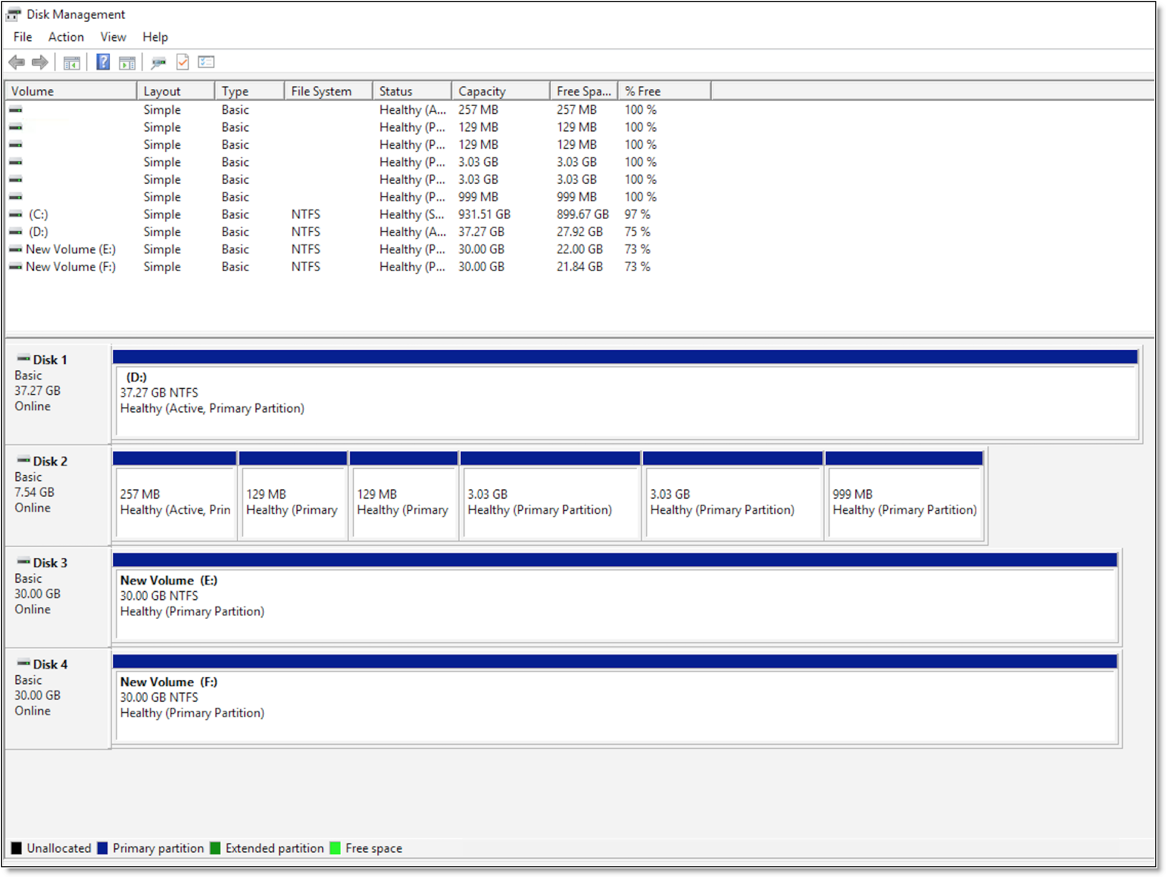
1. In the Windows Server Manager console, choose Tools > Computer Management > Storage > Disk Management and bring the mounted disk online.
Figure: Bringing the mounted disk online
2. Run the diskpart command using the Windows command line.
Figure: Setting disk volume attributes
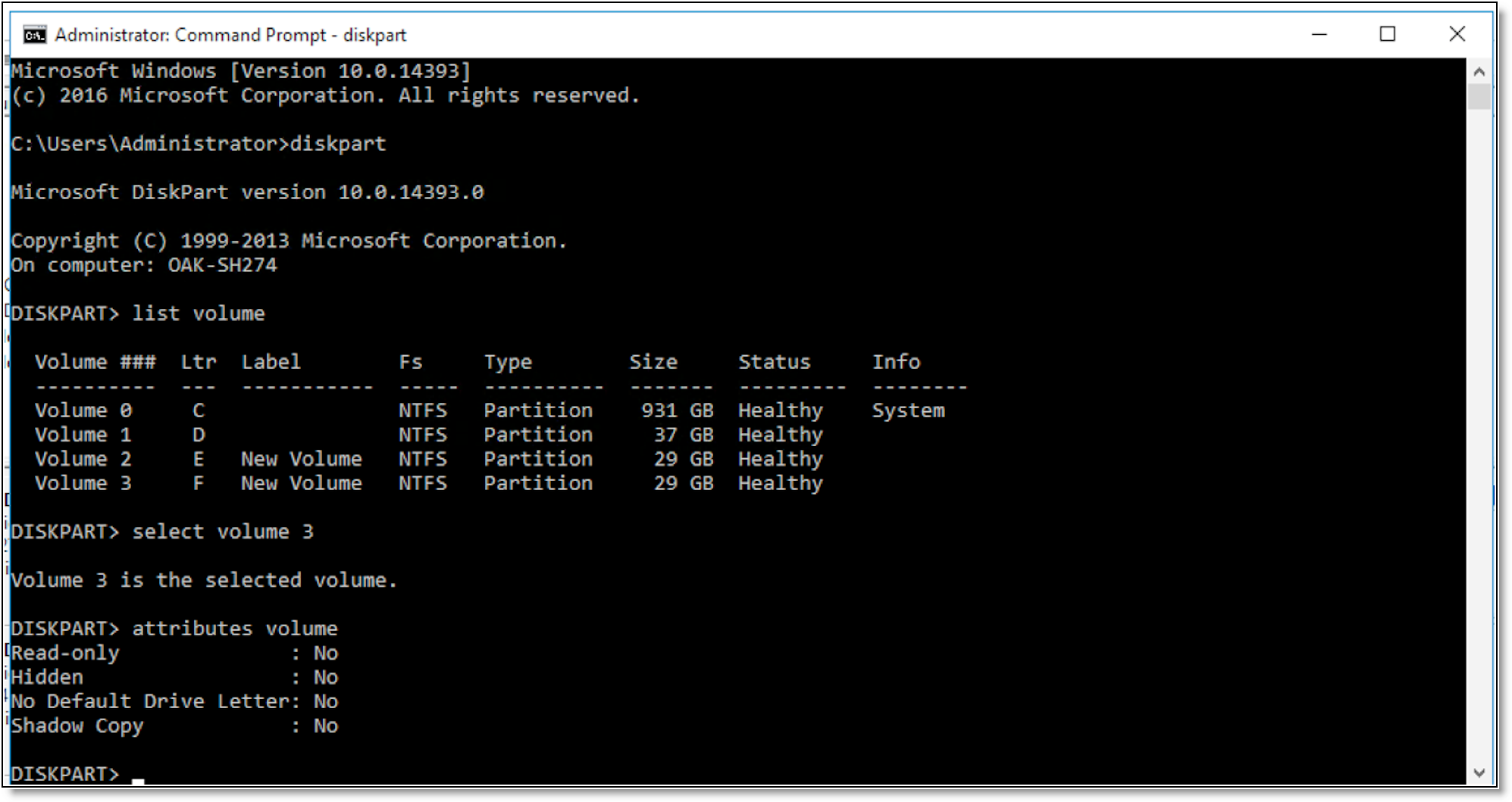
3. Run the select volume <volume-number> command, where <volume-number> specifies the volume number used to identify the disk volume.
4. Run the attributes volume command and set the value No for the Read-only, Hidden, No Default Drive Letter, and Shadow Copy attributes of the selected volume.
5. Bring the disk offline after setting the attributes for the disk volume and then bring the disk online.
6. Delete the VM that is already registered with the LUN.
Restoring the VM on Hyper-V
To restore the VM
1. Create a new folder to restore the VM.
2. In the Hyper-V Manager console, right-click the host and select Import Virtual Machine.
3. In the Import Virtual Machine wizard, click Next.
4. Specify the folder that contains the VM to import and click Next.
5. Select the VM to import and click Next.
6. Select the import type Restore the virtual machine (use the existing unique ID) and click Next.
7. Select the restore directory as destination folder and click Next.
8. Select the folder that contains the virtual hard disk (.vhdx file) and click Next.
9. Select the folder to store the imported virtual hard disk and click Next.
10. Review the summary and click Finish.
11. Start the VM and verify if the VM is restored successfully.
Troubleshooting
Connection to Hyper-V or Windows for data protection remains in the not connected state - If the DNS hostname and computer name of the Hyper-V or Windows host are different, the connection to Hyper‑V or Windows for data protection will not be successful. To avoid this issue, configure the Hyper-V or Windows server with the same DNS hostname and computer name.