Installing Virtual Edge
This chapter describes how to install the Virtual Edge appliance. It includes these sections:
Caution: Read and follow the safety guidelines described in the Safety and Compliance Guide. Failure to follow these safety guidelines can result in damage to the equipment.
Prerequisites
Before you install Virtual Edge software on Hyper-V, ensure these system requirements and configurations:
System requirements
Before you install and configure Virtual Edge on Hyper-V, ensure the minimum hardware and software system requirements described in this section.
Hardware requirements
This table summarizes the hardware requirements for the VSFH1100 and VSFH1200 appliances.
Hardware requirements | VSFH1100 | VSFH1200 |
Data Center | • Physical Core (model SFCR3500) in Hyper-V hypervisor mode Note: Virtual Cores are not supported. • SteelHead | • Physical Core (model SFCR3500) in Hyper-V hypervisor mode Note: Virtual Cores are not supported. • SteelHead |
HDD volume | • RAID10 • 1126 GiB (1.5 TB) Includes space for both the Virtual Edge and blockstore Virtual Hard Disks (VHDX). | • RAID10 • 5222 GiB (5.5 TB) Includes space for both the Virtual Edge and blockstore Virtual Hard Disks (VHDX). |
SSD volume | • RAID10 • 256 GiB | • RAID10 • 800 GiB |
RAID controller | • RAID10 • Battery backed Example: HPE Smart Array P408i-a SR Gen10 Controller | • RAID10 • Battery backed Example: HPE Smart Array P408i-a SR Gen10 Controller |
CPU cores | 4 x 1.5 GHz (minimum requirement for Virtual Edge) Note: Additional cores are required for compute VMs and host Windows Server. | 6 x 2 GHz (minimum requirement for Virtual Edge) Note: Additional cores are required for compute VMs and host Windows Server. |
Memory | 16 GB (minimum requirement for Virtual Edge) Note: Additional memory is required for compute VMs, host OS, and VM overhead sizing. For more information about memory overheads, see Understanding memory overheads. | 48 GB (minimum requirement for Virtual Edge) Note: Additional memory is required for compute VMs, host OS, and VM overhead sizing. For more information about memory overheads, see Understanding memory overheads. |
Speed | 1500 | 2000 |
Virtualization support | BIOS/UEFI, processor with hardware virtualization support, and SLAT support | BIOS/UEFI, processor with hardware virtualization support, and SLAT support |
Network interface cards (NICs) | 6 NICs (minimum requirement for non-HA setups) The 6 NICs are distributed as: • 4 for Virtual Edge • 2 for compute VMs (each NIC port is of 1 GbE) Note: For HA setups, you need additional NICs as required. | 6 NICs (minimum requirement for non-HA setups) The 6 NICs are distributed as: • 4 for Virtual Edge • 2 for compute VMs (each NIC port is of 1 GbE) Note: For HA setups, you need additional NICs as required. |
Virtual switches | 4 (minimum requirement) | 4 (minimum requirement) |
Supported bypass cards | • NIC-1-001G-4TX-BP (Four-Port 1-GbE Copper Base-T card) • NIC-1-001G-4SX-BP (Four-Port 1-GbE Fiber SX card) | • NIC-1-001G-4TX-BP (Four-Port 1-GbE Copper Base-T card) • NIC-1-001G-4SX-BP (Four-Port 1-GbE Fiber SX card) |
Hardware recommendations
In addition to the minimum hardware requirements, we recommend you ensure these requirements and configurations to successfully deploy and manage Virtual Edge on Hyper-V:
• Additional CPU cores are required for compute VMs and host Windows Server.
• Additional memory and storage resources are required for compute VMs, host OS, and VM overhead sizing. For more information about memory overheads, see
Understanding memory overheads.
• Root VHDX, blockstore, and segstore must be present on the battery backed RAID volumes. Not ensuring this requirement can result in deployment failure or malfunction.
• The blockstore and segstore VHDX files should be placed on separate volumes dedicated for Virtual Edge. Do not store any other VMs or files on the volumes dedicated for Virtual Edge.
• Do not place all the virtual hard disks into the same drive or disk. Do not use different file system types for the disks hosting blockstore and segstore.
Software requirements
This table summarizes the software requirements for the Virtual Edge deployment on Hyper-V.
Software requirements | Description |
Host operating system | Windows Server 2016 Standard Edition or Data Center Edition Version 1607. Note: Hyper-V role must be enabled on the Windows server. |
Guest VM operating system | Supports these Windows Server editions with NTFS-formatted volumes: • Windows Server 2012 • Windows Server 2012 R2 • Windows Server 2016 We recommend you to install Virtual Edge and branch VMs on the NTFS file system. Note: For Virtual Edge on Hyper-V deployments, prefetch optimization is supported only for Windows Server 2016 and Windows Server 2012 R2 guest VMs with NTFS volumes. |
Windows Remote Management (WinRM) | Enabled on Windows Server 2016. Note: WinRM is enabled during Virtual Edge installation. Do not disable WinRM. |
Riverbed plugins | Riverbed plugins installed on all the VMs. |
iSCSI traffic | iSCSI traffic on external virtual switches. |
Hyper-V Integration Services | The Windows Server 2016 compatible packages of Hyper-V Integration Services installed and running within guest VMs. Data Exchange Service (also called as KVP) is enabled during Virtual Edge installation. |
Volume Shadow Copy Service (VSS) | Installed and running on host Windows Server 2016 and guest VMs if you plan to protect data for Hyper-V and Windows servers. |
Understanding memory overheads
The minimum memory required is 16 GB for the VSFH1100 (1 TB) model and 48 GB for the
VSFH1200 (5 TB) model. In low-memory scenarios, the Virtual Edge may not start even if the available memory is more than the minimum required memory. It is important to understand these memory overheads before you allocate sufficient memory for Virtual Edge deployments:
• Host memory reserve - This is also known as root partition memory reserve. Based on the physical RAM capacity, the Hyper-V Dynamic Memory Balancer reserves additional memory for the Hyper-V host. The Hyper-V host uses this reserved memory to manage dynamic memory requirements of the guest VMs. This reserved memory is usually more than the memory used by the Hyper-V host. Typically, the host memory reserve is 2.5 GB for a server with a 32-GB physical RAM and 4 GB for a server with a 64-GB physical RAM. As a result of the host memory reserve, the memory available for the guest VMs will be less than the required memory.
To view the exact memory available for the guest VMs, run this command on the PowerShell CLI:
Get-Counter -Counter "\Hyper-V Dynamic Memory Balancer(*)\Available Memory"
• Guest VM memory overhead - Hyper-V assigns additional memory for every guest VM to manage memory requirements from guest integration services and other virtualization services.
The guest VM memory overhead is calculated as 32 MB + 8 MB per GB of memory assigned to it.
Note: The memory overheads are applicable for any guest VM running on Hyper-V and are not specific for the Virtual Edge on Hyper-V deployments.
The Riverbed Virtual SteelFusion Edge installer validates the memory available on Hyper-V considering the minimum memory requirements and the memory overheads. The installer displays an error message if the available memory is less than the memory required for successful Virtual Edge deployment on Hyper-V.
Setting up virtual switches
Before you install Virtual Edge, ensure that a minimum of four external virtual switches are created. Ensure that the NICs used for Virtual Edge are not shared. Assign an IP address to the AUX interface to manage the Virtual Edge appliance. For more information about creating virtual switches, see
https://docs.microsoft.com/en-us/windows-server/virtualization/hyper-v/get-started/create-a-virtual-switch-for-hyper-v-virtual-machines.
If you plan to use the bypass card, you need to create internal and external virtual switches and attach them to the physical interfaces of the bypass card. For more information, see
Configuring the Riverbed bypass card.
To assign an IP address to a Hyper-V Virtual Switch
1. Choose Start > Control Panel > Network and Internet > Network Connections.
Figure: Assigning an IP address to a virtual switch

2. Double-click the internal virtual switch Hyper-V Virtual Ethernet Adapter.
The virtual switch name appears in brackets.
3. Under the Networking tab in the Ethernet Properties window, select Internet Protocol Version 4 (TCP/IP) and click Properties.
4. Configure the IP and DNS settings and click OK.
Installing Riverbed Hardware Snapshot Provider
You need to install Riverbed Hardware Snapshot Provider (RHSP) version 6.0 or later on the host Windows Server if you plan to use data protection services. Double-click the Windows installer file and follow the wizard instructions to install RHSP.
Disabling write caching on disk drives
We recommend you disable write caching on SSD and HDD to prevent data loss from the disks.
To disable write caching on disk drives
1. Choose Computer Management > Device Manager.
Figure: Disabling write caching on disk drives
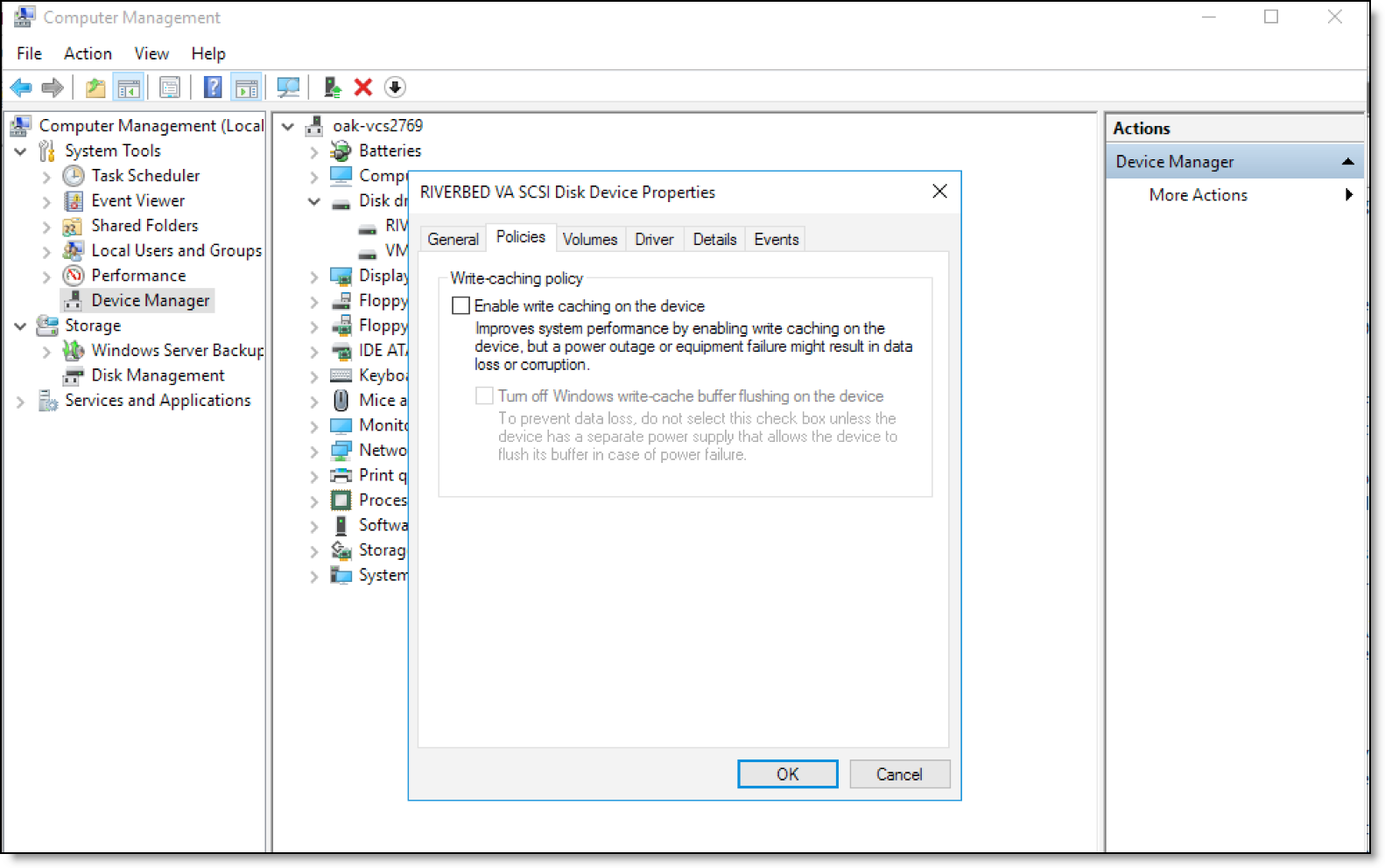
2. Right-click the disk drives on which you want to deploy Virtual Edge and click Properties.
3. Under the Policies tab in the SCSI Disk Device Properties window, clear the Enable write caching on the device check box.
4. Click OK to save the settings.
Installing Virtual Edge on Hyper-V
Before you install Virtual Edge software on Hyper-V, ensure that you have set up and configured the system to meet all the preinstallation requirements. For more information about the installation prerequisites, see
Prerequisites.
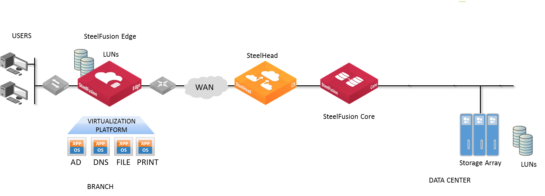
Position your Edge appliances as close as possible to your network endpoints—that is, branch office Edge appliances should be as close to your clients as possible, and data center SteelFusion Cores should be as close to your storage arrays as possible to maximize performance and minimize latency.
Ideally, Edge appliances optimize only traffic that is initiated or terminated at their local site. We recommend that you deploy the Edge appliances where the LAN connects to the WAN, and not where any LAN-to-LAN or WAN-to-WAN traffic can pass through (or be redirected to) the Edge appliance.
For more information about your deployment options and best practices for deploying Edge appliances, see the SteelFusion Design Guide.
Figure: SteelFusion Edge in-path deployment
Note: If you plan to use the bypass card, we recommend you create the required internal and external virtual switches before you install Virtual Edge on Hyper-V. For more information, see
Configuring the Riverbed bypass card.
To install Virtual Edge
1. Download the Riverbed_Virtual_SteelFusion_Edge_<model-number>.exe file from the Riverbed Support site.
Where, <model-number> specifies one of the supported Virtual Edge models (VSFH1100 or VSFH1200). For more information about supported Virtual Edge models, see
System requirements.
2. Double-click the downloaded EXE file and follow the instructions to install Virtual Edge.
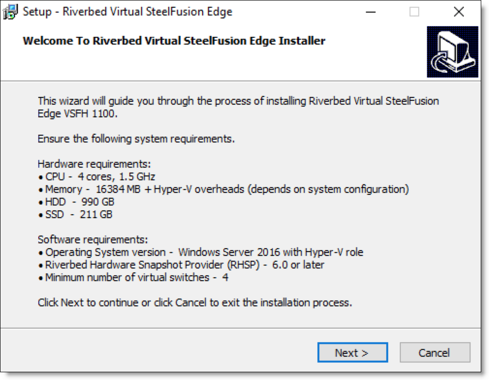
3. Review the system requirements on the Welcome page of the installation wizard and click Next.
Figure: Installation welcome page
4. Read and accept the license agreement; click Next to continue.
5. Click Yes to acknowledge that your system meets all the requirements to install and configure Virtual Edge on Hyper-V.
6. Specify the installation location, HDD RAID disk drive, and SDD RAID disk drive details and click Next.
Figure: Installation location
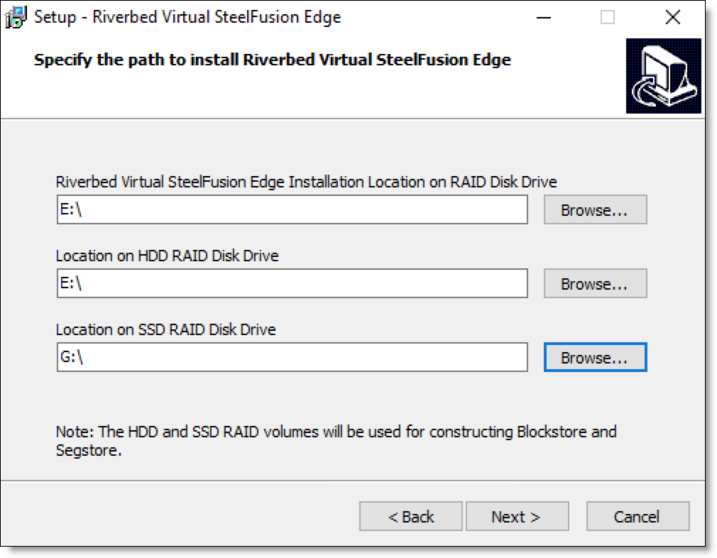
The HDD and SDD disk drives are used for constructing blockstore and segstore.
You must install Virtual Edge on a RAID disk drive.
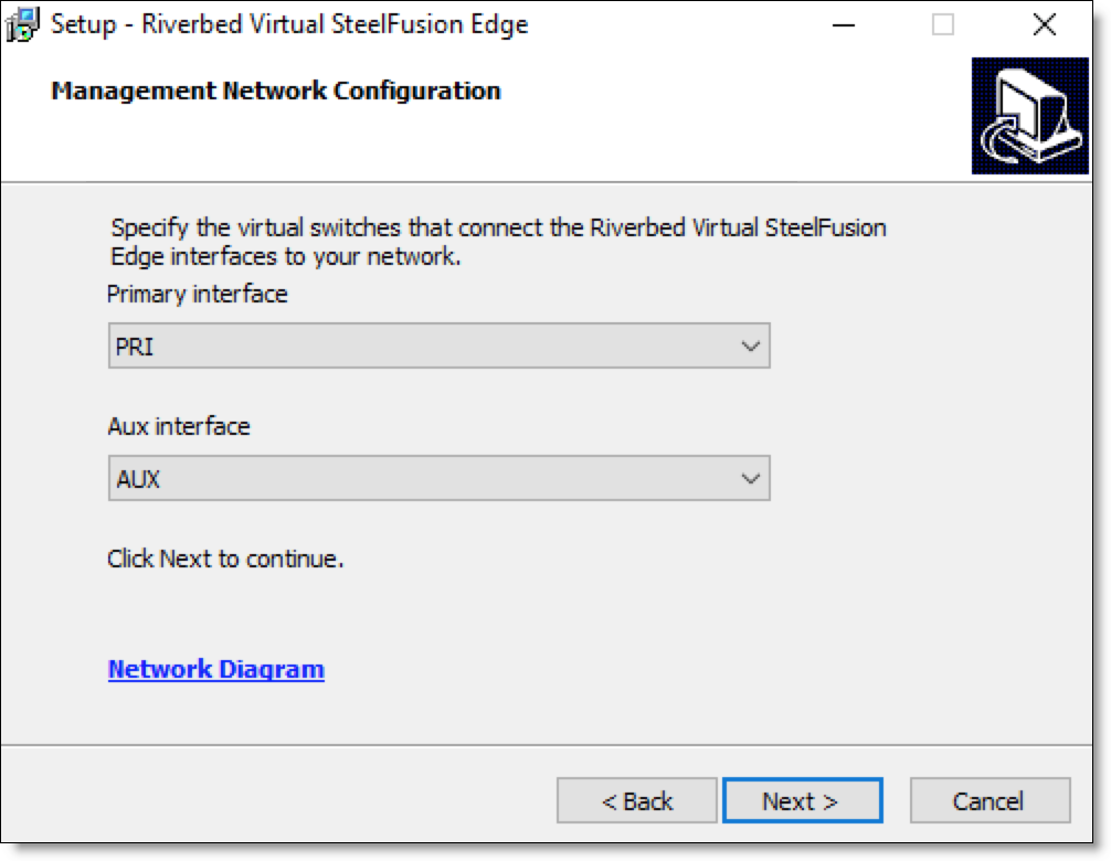
7. Select the primary and auxiliary management network interfaces and click Next.
Figure: Management Network Configuration page
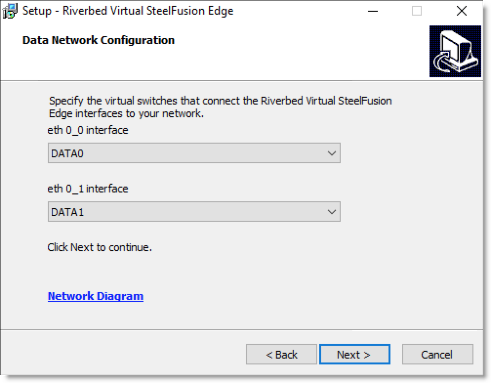
8. Select the data network interfaces and click Next.
Figure: Data Network Configuration page
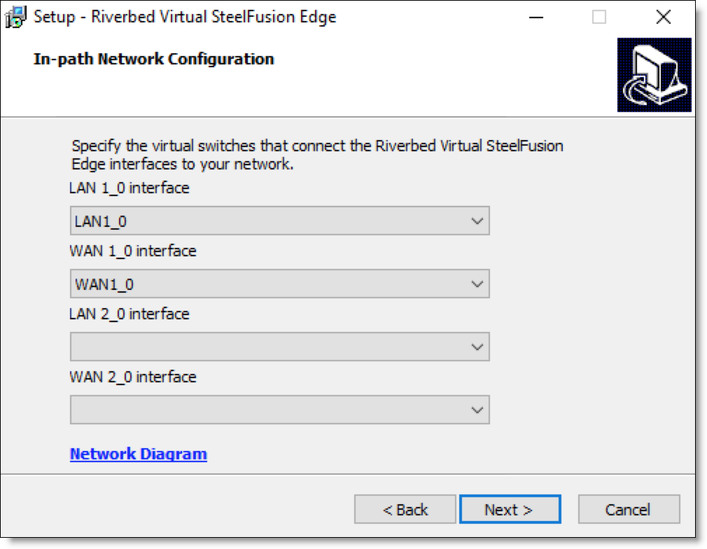
9. Select the in-path network interfaces and click Next.
Figure: In-path Network Configuration page
10. Review the installation settings summary and click Install.
Wait for the installation process to complete. The installation time may vary depending on your system resources.
Configuring the Riverbed bypass card
Complete the steps described in this section to configure the Riverbed bypass card on Hyper-V and make it available to the Virtual Edge VM. For more information about the supported bypass cards, see
Hardware requirements.
Before you begin
Ensure these prerequisites before you configure the Riverbed bypass card:
• The bpvmctl service is started and running.
Note: If you plan to use the bypass card, we recommend you create the required virtual switches before you install Virtual Edge on Hyper-V.
Basic steps for configuring the Riverbed bypass card
This section provides an overview of the basic steps to be carried out to configure the Riverbed bypass card on Hyper-V and make it available to the Virtual Edge VM. Detailed procedures are provided in the sections that follow.
Task | Reference |
1. Create an internal virtual switch and attach it to the management interface of the bypass card. | |
2. Create external virtual switches and attach them to the LAN and WAN interfaces of the bypass card. | |
3. Map virtual NICs of Virtual Edge to the virtual switch interfaces of the bypass card. | |
4. Map a Virtual Edge network adapter to the management interface of the bypass card. | |
Creating an internal virtual switch for the management interface of the bypass card
Create an internal virtual switch and attach it to the management interface of the bypass card.
To create an internal virtual switch
1. In the Hyper-V Manager console, right-click the host server and select Virtual Switch Manager to open the Virtual Switch Manager window.
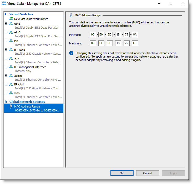
2. Under Global Network Settings, select MAC Address Range. Define the MAC address range from 00:E0:ED:18:75:8A to 00:EE:ED:18:75:FF and click OK.
Figure: Virtual Switch Manager - MAC Address Range
3. Under the Virtual Switches section of the Virtual Switch Manager, select New virtual network switch.
4. In the Create virtual switch pane, select Internal and click Create Virtual Switch.
5. In the Virtual Switch Properties pane, enter a friendly name for the virtual switch, such as BP-management interface.
Figure: Virtual Switch Manager - Internal network Virtual Switch Properties
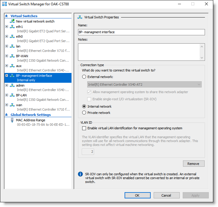
6. Under Connection type, select Internal network.
7. Click OK to create the virtual switch.
8. Choose Start > Control Panel > Network and Internet > Network and Sharing Center to verify that the vEthernet (BP-management interface) is configured with the MAC address 00:E0:ED:18:75:8A.
This is the first MAC address in the address range you defined in
Step 2.
Creating external virtual switches for the LAN and WAN interfaces of the bypass card
Create external virtual switches and attach them to the physical LAN and WAN interfaces of the bypass card.
To create external virtual switches
1. Under the Virtual Switches section of the Virtual Switch Manager, select New virtual network switch.
2. In the Create virtual switch pane, select External and click Create Virtual Switch.
3. In the Virtual Switch Properties pane, enter a friendly name for the virtual switch, such as BP-LAN.
4. Under Connection type, select External network and select one of the bypass card interfaces from the list of available interfaces.
Figure: Virtual Switch Manager - External network Virtual Switch Properties
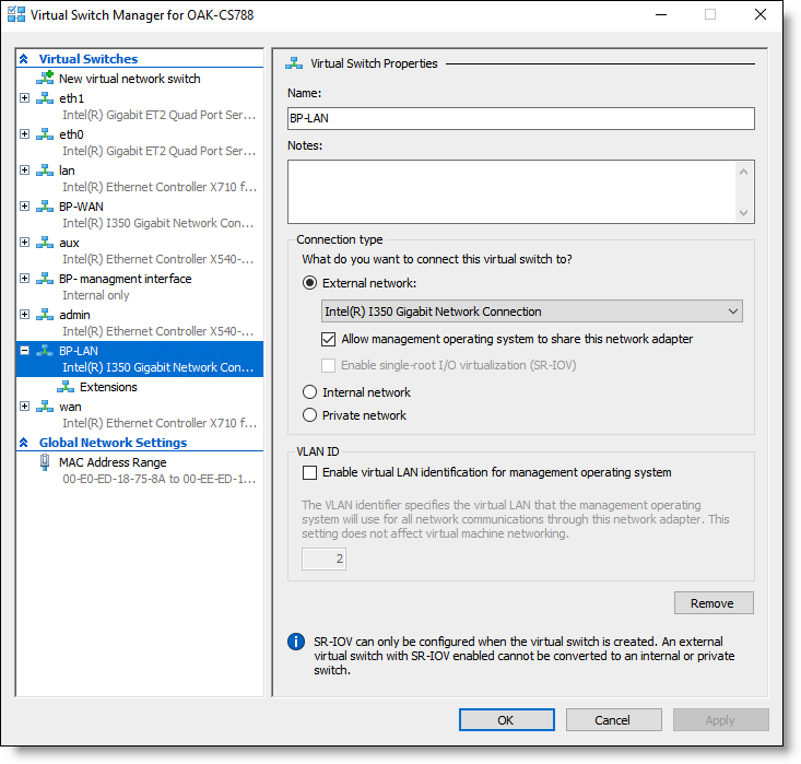
5. Select the Allow management operating system to share this network adapter check box.
6. Click OK to create the external virtual switch for the LAN interface of the bypass card.
7. Repeat
Step 1 to
Step 6 to create another external virtual switch (BP-WAN) for the WAN interface of the bypass card.
Mapping virtual NICs of Virtual Edge to the virtual switch interfaces of the bypass card
Install Virtual Edge and map the virtual NICs of Virtual Edge to the virtual switch interfaces you created for the bypass card.
To map virtual NICs of Virtual Edge to virtual switches of the bypass card
1. Install Virtual Edge on Hyper-V.
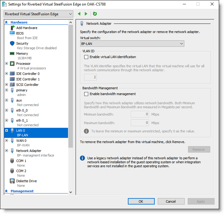
2. During Virtual Edge Installation, map the LAN 0 and WAN 0 interfaces of Virtual Edge to the BP-LAN and BP-WAN interfaces of the bypass card you created.
Figure: Riverbed Virtual SteelFusion Edge settings - mapping LAN 0 to BP-LAN
3. Complete the Virtual Edge installation process.
After installing Virtual Edge on Hyper-V, do not power on the Virtual Edge VM on Hyper-V.
4. In the Hyper-V Manager console, right-click the Riverbed Virtual SteelFusion Edge VM and select Settings.
5. Under Hardware, select LAN 0 > Advanced Features and change the last octet of the MAC address to A1.
Figure: Riverbed Virtual SteelFusion Edge settings - Static MAC Address
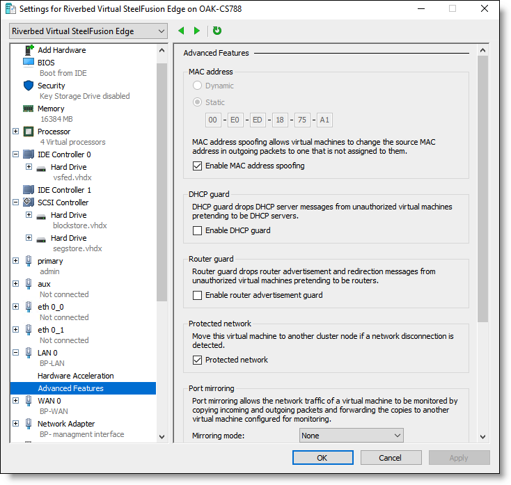
6. Select the Enable MAC address spoofing check box.
7. Click OK to save the settings.
8. Select WAN 0 > Advanced features and change the last octet of the MAC address to A2.
9. Select the Enable MAC address spoofing check box and click OK to save the settings.
Mapping a Virtual Edge network adapter to the management interface of the bypass card
Create a new network adapter in Virtual Edge and map it to the management interface of the bypass card. Do not power on the Virtual Edge VM before you perform this task.
Note: Hyper-V allows only eight standard virtual NICs per VM. To create a new network adapter, you need to remove the network adapters corresponding to the additional LAN and WAN (second LAN-WAN pair) interfaces from the Virtual Edge VM.
To map a network adapter in Virtual Edge to the management interface of the bypass card
1. In the Hyper-V Manager console, right-click the Riverbed Virtual SteelFusion Edge VM and select Settings.
2. Under Hardware, select the LAN 1 interface. In the Network Adapter pane, click Remove to remove the LAN 1 interface.
Removing unused virtual NICs lets you create a new network adapter because Hyper-V allows you to create a maximum of 8 standard virtual NICs per VM.
3. Select the WAN 1 interface. In the Network Adapter pane, click Remove to remove the WAN 1 interface.
4. Under Hardware, select Add Hardware.
5. In the Add Hardware pane, select Network Adapter from the list of devices and click Add.
Figure: Riverbed Virtual SteelFusion Edge settings - Network Adapter configuration
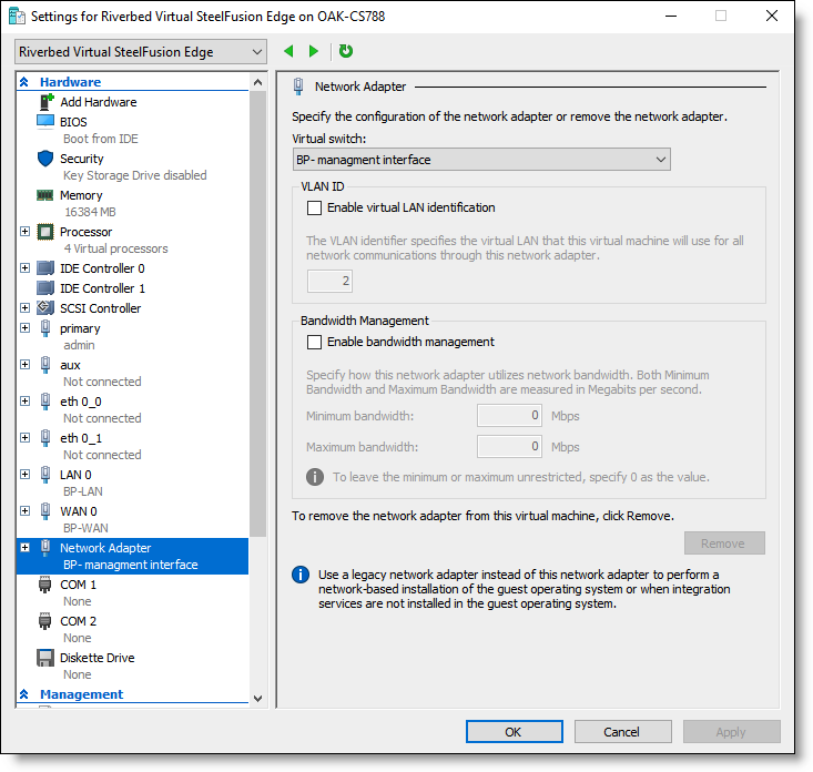
6. Select BP-management interface from the Virtual switch drop-down list and click OK.
7. Select Network Adapter > Advanced Features.
8. In the MAC address section, select Dynamic.
9. Select the Enable MAC address spoofing check box and click OK to save the settings.
Performing post-installation tasks
The Riverbed Virtual SteelFusion Edge VM is created on Hyper-V during Virtual Edge installation. Perform these post-installation steps to ensure that the installation process is complete and you are able to access the Virtual Edge VM.
If you use the bypass card in your deployment, you need to perform these tasks before you power on the Virtual Edge VM:
To connect to the Virtual Edge VM using the Hyper-V Manager
1. In the Hyper-V Manager console, select the Windows server and verify if the Riverbed Virtual SteelFusion Edge VM is created.
Figure: Hyper-V Manager - Riverbed Virtual SteelFusion Edge VM
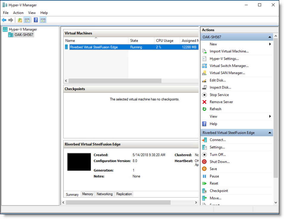
2. Power on the VM.
After installation, the Riverbed Virtual SteelFusion Edge VM is in powered off state. You need to power on the Virtual Edge VM using the Hyper-V Manager.
3. Right-click the VM and select Connect to connect to the VM console.
Uninstalling Virtual Edge
Uninstalling Virtual Edge in production deployments can result in loss of configuration and data. However, you can uninstall Virtual Edge in the event of incomplete installation or installation failure.
Before you begin
Perform these tasks before you uninstall Virtual Edge:
• Ensure that the Virtual Edge is not serving any branch hosts and there is no uncommitted data in the blockstore.
• Disconnect any configured Core from the Virtual Edge.
• Disconnect any configured HA peer from the Virtual Edge.
• Power off the Riverbed Virtual SteelFusion Edge VM using Hyper-V Manager.
Note: After you uninstall Virtual Edge, the Virtual Edge files and configuration are removed from Hyper-V. If you install Virtual Edge again, you need to perform all the required installation and configuration tasks.
To uninstall Virtual Edge
1. In the Windows host, choose Start > Control Panel > Programs > Programs and Features.
2. Select Riverbed Virtual SteelFusion Edge 6.0.0 and click Uninstall.
3. Click Yes to confirm.
4. Click OK to complete the uninstallation process.
Connecting the Edge to your network
You use standard Ethernet straight-through and crossover cables to connect to your network in an in-path configuration. This table summarizes the correct cable usage when you are connecting LAN and WAN ports or when you are connecting data ports.
Device | Cable |
Edge appliance to a switch | Straight-through (for example, primary and LAN ports on the appliance to the LAN switch) |
Edge appliance to a router | Crossover (for example, WAN port on the appliance to the WAN router) |
Edge appliance to a host | Crossover (for example, LAN and WAN ports on the Edge appliance bypass cards act like host interfaces during normal operation) |
Edge appliance to an Edge appliance | Crossover |
For more information about cabling best practices, see the SteelFusion Design Guide.
To connect the appliance to your network
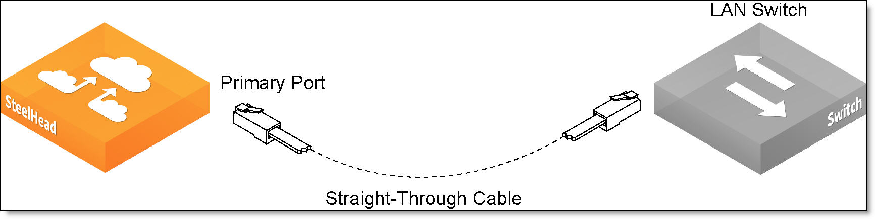
1. Plug the straight-through cable into the primary port of the appliance and the LAN switch.
Figure: Connecting the primary port to the LAN switch
2. Identify the straight-through cable that connects your LAN switch to your WAN router. Unplug the end connected to the WAN router.
Figure: Disconnecting the WAN router
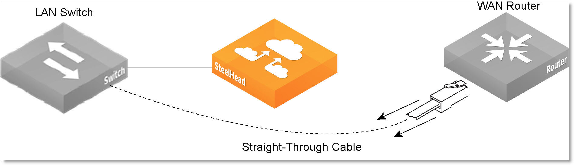
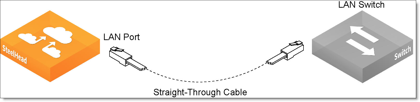
3. Plug the straight-through cable that you disconnected from the WAN router into the LAN port of the appliance.
Figure: Connecting the LAN switch to the LAN port
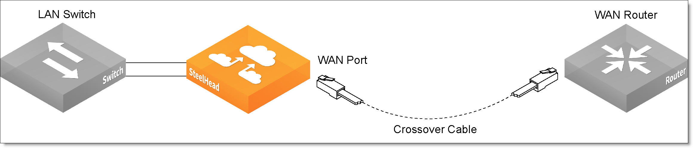
4. Using the provided crossover cable, plug the cable into the WAN port of the appliance and the WAN router.
Figure: Connecting the WAN port to the WAN router
Note: If you have four-port bypass cards, repeat
Step 1 to
Step 4.