Replacing SteelFusion Edge Components
This chapter describes how to replace components in SteelFusion Edge appliances. It includes the following sections:
Field-replaceable units
The SteelFusion Edge appliances contain several field-replaceable units (FRUs) that you or a certified service technician can troubleshoot, remove from the system, and replace without having to send the system to a repair facility.
Caution: Perform troubleshooting or repairs only as directed in the product documentation or by the online or telephone service and support team. All other servicing should be performed by a certified technician. Your warranty does not cover damage due to servicing that is not authorized by Riverbed.
The following table lists the FRUs available for the SteelFusion Edge appliances.
FRU | Description | SFED Appliance | Instructions |
MEM-1-002 | 8 GB DRAM DIMM | 2100, 2200, 3100, 3200, 5100 | |
MEM-1-003 | 16 GB 1600, x4/DR, 16 GB RAM | 2100, 2200, 3100, 3200, 5100 | |
MEM-1-004 | 32 GB DRAM DIMM | 5100 | |
HDD-2-002 | 3.5-inch 1-TB SATA | 2100 | |
HDD-2-003 | 3.5-inch 2-TB SATA | 2200, 3100, 3200 | |
HDD-2-006 | 3.5-inch 4-TB SATA | 5100 | |
SSD-2-002 | 100–120 GB | 2100, 2200 | |
SDD-2-004 | 200–240 GB SSD | 3100, 3200 | |
SSD-2-006 | 400–480 GB SSD | 5100 | |
PWS-2-AC-1U | 770 Watt PSU AC -1U | 2100, 2200 | |
PWS-2-AC-2U | 1000 Watt PSU AC -2U | 3100, 3200, 5100 | |
FAN-2-1U-KIT | Fan assembly, 1U, bank of 2x6, 12 fans with the 6 cables/connectors | 2100, 2200 | |
FAN-2-2U-KIT | Fan assembly, 2U, 1 cableless pluggable, consists of 2 fans | 3100, 3200, 5100 | |
RMK-2-EXPRAIL | Rack kit, 1U and 2U, fully extendable | 2100, 2200, 3100, 3200, 5100 | |
BZL-2-1U | 1U locking/hinged Bezel Replacement Kit | 2100, 2200 | |
BZL-2-2U | 2U locking/hinged Bezel Replacement Kit | 3100, 3200, 5100 | |
Required tools
You need the following tools and equipment to replace components:
• You must use approved components for the appliance to function properly. Installation of unapproved components will result in boot failure. To order appliance components, contact Riverbed Support at https://support.riverbed.com.
• An antistatic strap. When you replace components, you must wear a grounded ESD antistatic strap to protect the hardware against electrostatic discharge. Make sure that the strap makes skin contact prior to handling equipment.
• A magnetic Phillips screwdriver.
Opening the bezel
The bezel on the SteelFusion Edge appliances is attached to the front panel.
To open and remove the bezel on SteelFusion Edge appliances
Figure: Opening the bezel on SteelFusion Edge appliances
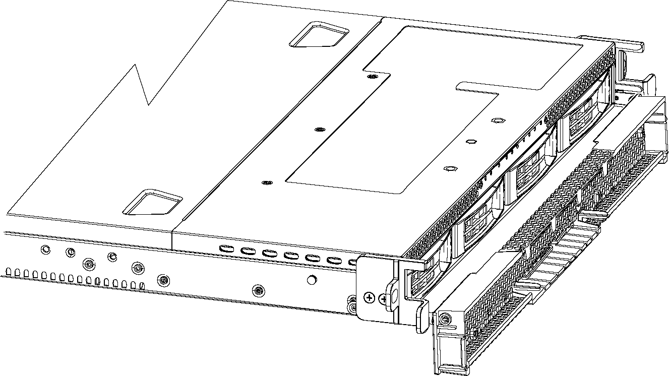
Figure: Screw location on the hinge
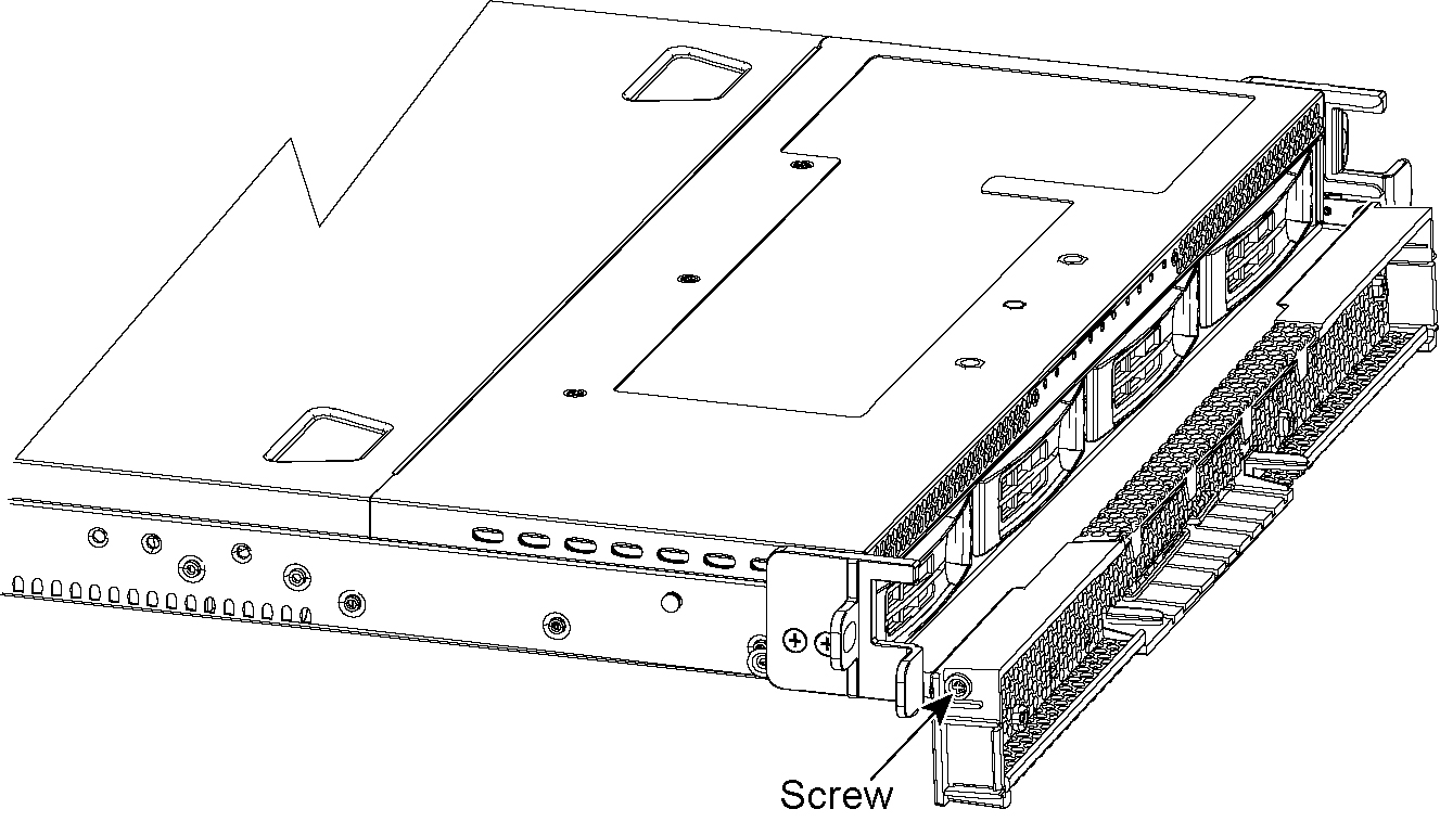
3. Place the new bezel between the hinges and tighten the screws on both sides to secure the bezel to the hinges.
4. Flip the bezel up to put it in the closed position.
Removing the chassis cover
This section describes how to remove the chassis cover on SteelFusion Edge appliances. It includes the following procedures:
Removing the chassis cover on 1U appliances
This section describes how to remove the chassis covers for the SteelFusion Edge 2100 and SteelFusion Edge 2200 appliances.
To remove the chassis cover on 1U appliances
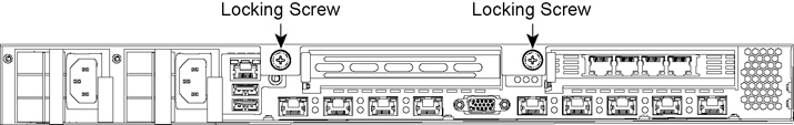
Figure: Loosening the locking screws
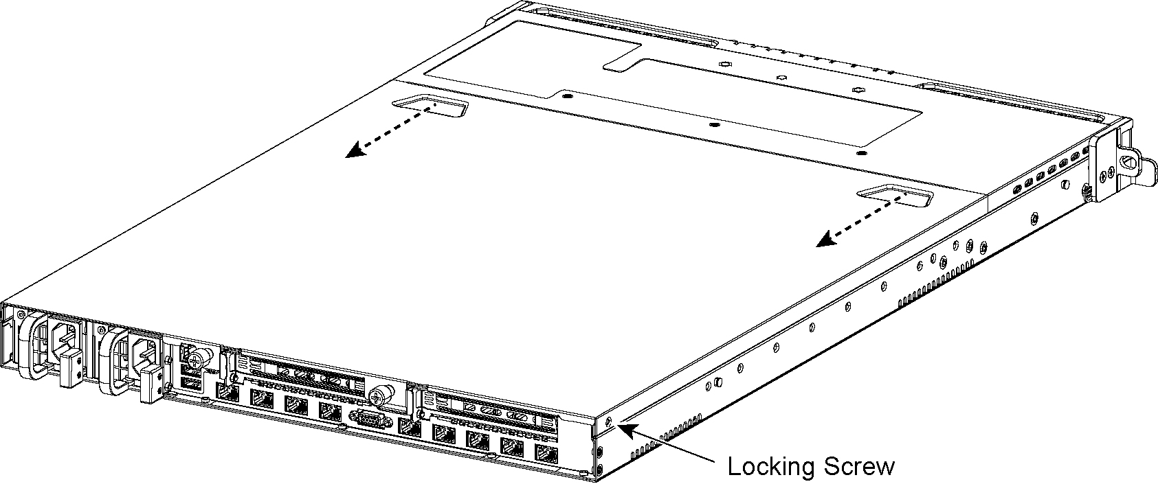
2. Remove the third locking screw on the left side near the back of the top cover.
Figure: Removing the chassis cover
Removing the chassis cover on 2U appliances
This section describes how to remove the chassis covers for the SteelFusion Edge 3100, SteelFusion Edge 3200, and SteelFusion Edge 5100 appliances.
To remove the chassis cover on 2U appliances
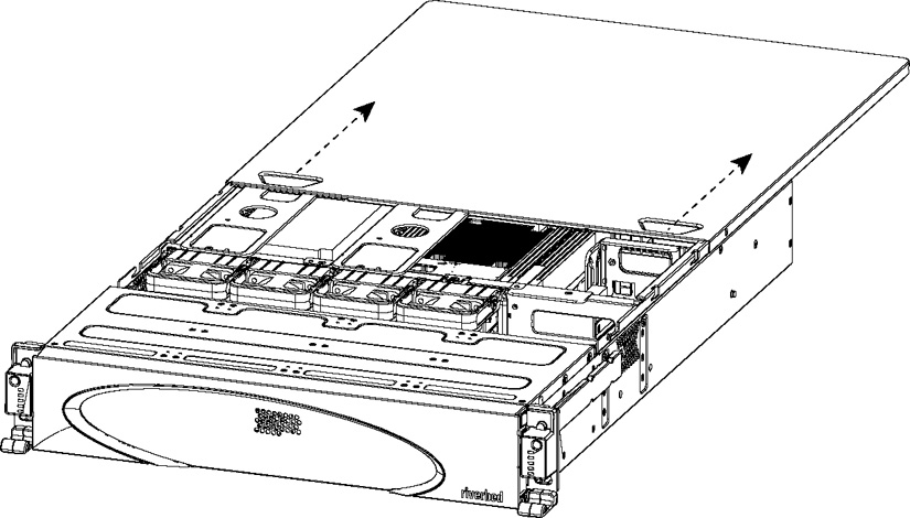
Figure: Loosening the locking screws
2. Remove the third locking screw on the right side of the top cover.
Figure: Removing the chassis cover
Replacing disk drives
This section describes how to remove and replace disk drives and includes the following procedures:
Note: If you need to replace an appliance, you cannot move the disks to preserve your data. Each disk is encoded with machine-level information, and moving disks is not supported.
Replacing disk drives in 1U SteelFusion Edge appliances
1U SteelFusion Edge appliances are equipped with replaceable, hot-swappable hard disk drives (HDD) and solid-state drives (SSD). The disk slot numbers for the drives are numbered in ascending order from left to right.
Figure: 1U SteelFusion Edge disk slot numbers
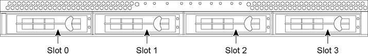
You must use approved disk drives. Slots 0 and 1 support HDD and slots 2 and 3 support SSD. The following table lists the disk drive configuration available for the 1U SteelFusion Edge appliances.
Appliance | Quantity | Slots supported |
SteelFusion Edge 2100 | 2 x 3.5-inch 1-TB HDD | 0 and 1 |
2 x 2.5-inch 100 GB– 120 GB SDD | 2 and 3 |
SteelFusion Edge 2200 | 2 x 3.5-inch 2-TB HDD | 0 and 1 |
2 x 2.5-inch 100 GB–120 GB SSD | 2 and 3 |
Note: When you replace disk drives, you must wear a grounded ESD antistatic strap to protect the hardware against electrostatic discharge. Make sure that the strap makes skin contact prior to handling equipment.
Caution: 
Use caution when you remove or replace components; they can become hot to the touch.
To replace the disk drive in 1U appliances
2. Identify the faulty disk drive.
3. Press the orange release button and pull the drive handle toward you.
Figure: Removing the disk drive
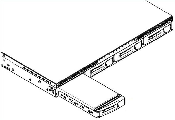
5. Slide in the new disk drive until it mates with the back connectors in the chassis.
The disk drive LED lights blue when connected.
6. Press in the disk-drive handle to close.
The new disk drive runs through a self-test automatically and then begins proper operation with the other disk drives. You do not need to set up or configure the new disk drive.
Note: It takes approximately 3 to 4 hours, depending on the system load, to rebuild a new disk drive. When the disk drive has finished rebuilding, the system sends an email to the administrator user.
Replacing disk drives in 2U SteelFusion Edge appliances
The 2U SteelFusion Edge appliances are equipped with replaceable, hot-swappable disk drives. The drives are numbered in ascending order from the upper-left corner to the lower-right corner. (See
Figure: 2U SteelFusion Edge disk slot numbers.)
Figure: 2U SteelFusion Edge disk slot numbers
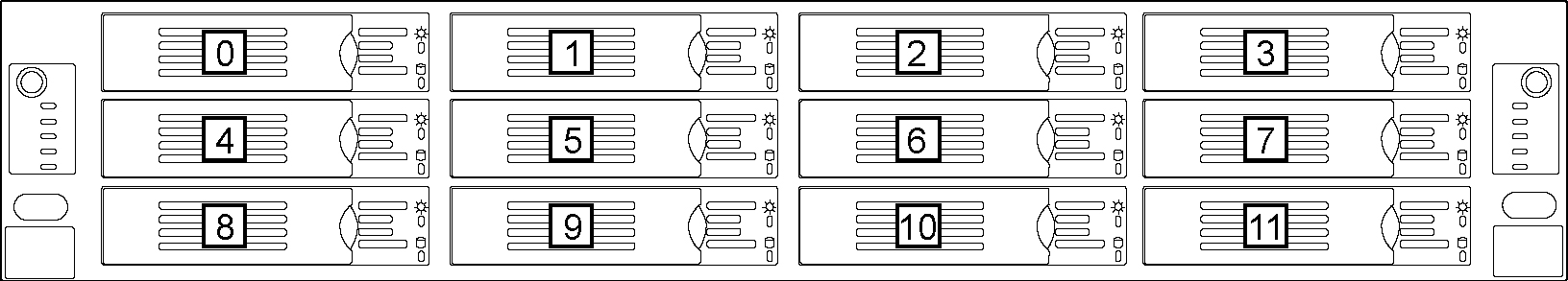
You must use approved disk drives. Slots 0 through 7 support HDD and slots 8 through 11 support SSD. The following table lists the disk drive configuration available for the 2U SteelFusion Edge appliances.
Appliance | Quantity | Slots supported |
SteelFusion Edge 3100 | 4 x 3.5-inch 2-TB HDD | 0 to 7 |
4 x 2.5-inch 200 –240 GB SDD | 8 to 11 |
SteelFusion Edge 3200 | 8 x 3.5-inch 2TB HDD | 0 to 7 |
4 x 2.5-inch 200 –240 GB SSD | 8 to 11 |
4 x 2.5-inch 240 –400 GB SSD | 8 to 11 |
SteelFusion Edge 5100 | 8 x 3.5-inch 4-TB HDD | 0 to 7 |
4 x 2.5-inch 400–480 GB SSD | 8 to 11 |
Note: When you replace disk drives, you must wear a grounded ESD antistatic strap to protect the hardware against electrostatic discharge. Make sure that the strap makes skin contact prior to handling equipment.
Caution: Use caution when you remove or replace components; they can become hot to the touch.
To replace a disk drive in the 2U SteelFusion Edge appliances
1. Open the bezel.
2. Identify the faulty disk drive.
The Alarm Status page in the Management Console identifies the faulty disk drive.
The disk drive LED is orange for failed drives.
3. Connect to the CLI and enter the raid swraid fail-disk command:
amnesiac> raid swraid fail-disk <slot-number>
This command ensures the RAID system removes the disk partitions before the drive is removed from the slot. For details, see the Riverbed Command-Line Interface Reference Manual.
Figure: Releasing the disk drive
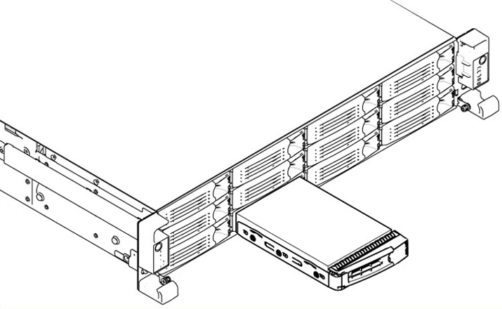
5. Slide the faulty disk drive out of the slot. Make sure you remove the correct drive.
6. Wait 60 seconds between removing the old drive and adding the new drive.
Waiting ensures the system detects the drive removal so it can rebuild properly after you insert the new drive. If you insert the new drive before the system detects the removal, data might be corrupted.
7. Open the new disk-drive handle by pressing the orange release button.
8. Slide in the new disk drive until it mates with the back connectors in the chassis.
The disk drive LED is blue when connected.
9. Press in the disk-drive handle to close.
The new disk drive runs through a self-test automatically and then begins proper operation with the other disk drives. You do not need to set up or configure the new disk drive.
Replacing power supply units
This section describes how to remove and replace a power supply unit in SteelFusion Edge appliances.
Replacing power supply units in 1U and 2U appliances
This section describes how to replace a power supply in SteelFusion Edge appliances. These appliances are equipped with replaceable, hot-swappable power supply units.
Caution: Use gloves when replacing the power supply units; they can become hot to the touch.
To replace power supply units in 1U and 2U appliances
1. Locate the defective power supply unit and remove the power cord.
Figure: Removing the power supply unit from a SteelFusion Edge appliance
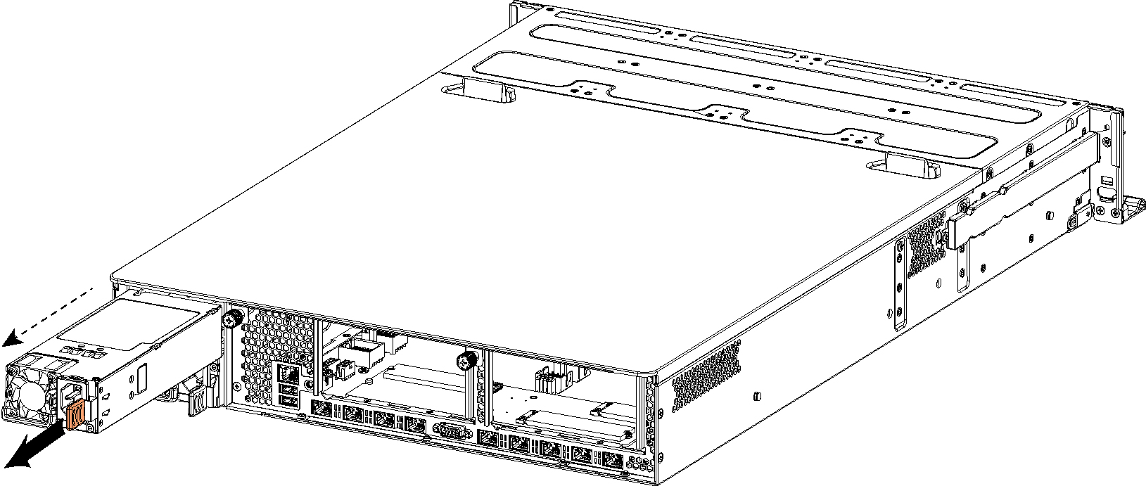
Note: Power Supply 1 (PS1) is on top, and Power Supply 2 (PS2) is on the bottom.
3. Pull the power supply unit out of the chassis.
Caution: Put the defective power supply unit aside; wait until it cools down before touching it.
4. Slide in the new power supply unit until it mates with the back connectors in the chassis.
When the power supply unit is pushed all the way in, the button clicks to the right.
5. Plug the AC power cord into the new power supply unit.
Adding and replacing memory modules
This section describes how to remove and replace existing memory modules and install additional memory modules in the SteelFusion Edge appliances. This section includes the following procedures:
Installing additional memory modules in SteelFusion Edge appliances
Additional memory kits are available with certain SteelFusion Edge appliances to increase the memory on the hypervisor node. This section describes how to add memory modules to the SteelFusion Edge 2100, 2200, and 3100 appliances.
The following diagram shows memory module slot locations in these appliances. (
Figure: Memory module slot locations.)
Figure: Memory module slot locations
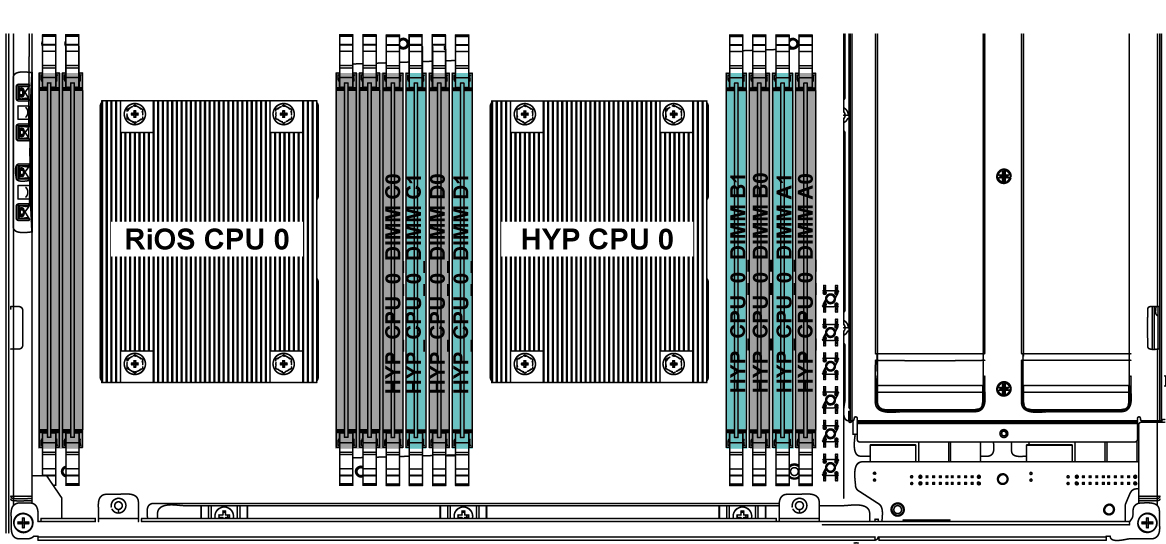
When adding memory to the SteelFusion Edge appliances, follow these guidelines:
• SteelFusion Edge 2100, install the 16 GB memory modules in the available black slots:
• HYP CPU 0 DIMM D0 (16 GB)
• HYP CPU 0 DIMM B0 (16 GB)
• SteelFusion Edge 2200, install the new 16 GB and 8 GB memory modules into the slots next to the existing module of the same size:
• HYP CPU 0 DIMM C1 (16 GB)
• HYP CPU 0 DIMM D1 (8 GB)
• HYP CPU 0 DIMM B1 (8 GB)
• HYP CPU 0 DIMM A1 (16 GB)
• SteelFusion Edge 3100, install the 16 GB modules in the available slots:
• HYP CPU 0 DIMM C1 (16 GB)
• HYP CPU 0 DIMM D1 (16 GB)
• HYP CPU 0 DIMM B1 (16 GB)
• HYP CPU 0 DIMM A1 (16 GB)
This table lists the memory slots and that are occupied by default (memory size indicated in black) and available for additional memory module installation (memory size indicated in red).
SFED | DIMM C0 | DIMM C1 | DIMM D0 | DIMM D1 | CPU | DIMM B1 | DIMM B0 | DIMM A1 | DIMM A0 |
2100 | 16 GB | | 16 GB | | | | 16 GB | | 16 GB |
2200 | 16 GB | 16 GB | 8 GB | 8 GB | | 8 GB | 8 GB | 16 GB | 16 GB |
3100 | 16 GB | 16 GB | 16 GB | 16 GB | | 16 GB | 16 GB | 16 GB | 16 GB |
Replacing memory modules in 1U SteelFusion Edge appliances
This section describes how to add and replace memory modules in SteelFusion Edge 2100 and SteelFusion Edge 2200 appliances. When replacing memory in the appliances, install the memory in the same slots.
The following diagram shows memory module slot locations in these appliances. (
Figure: Memory module slot locations in 1U SteelFusion Edge appliances.)
Figure: Memory module slot locations in 1U SteelFusion Edge appliances
To replace the memory modules in the 1U SteelFusion Edge appliances
1. Power down the appliance.
2. Remove the chassis cover.
Figure: Removing PCIe carrier locking screws
Figure: Removing PCIe carrier
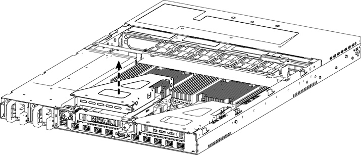
Figure: Removing cooling shroud screws
Caution: Lift the shroud straight up to avoid damaging any components of the appliance.
Figure: Accessing the memory modules
7. Remove the existing memory module and replace it with an approved memory module of the same size.
8. Align the memory-module edge connector with the slot alignment keys and insert it into the slot.
Figure: Inserting the memory modules into the connector slot and securing
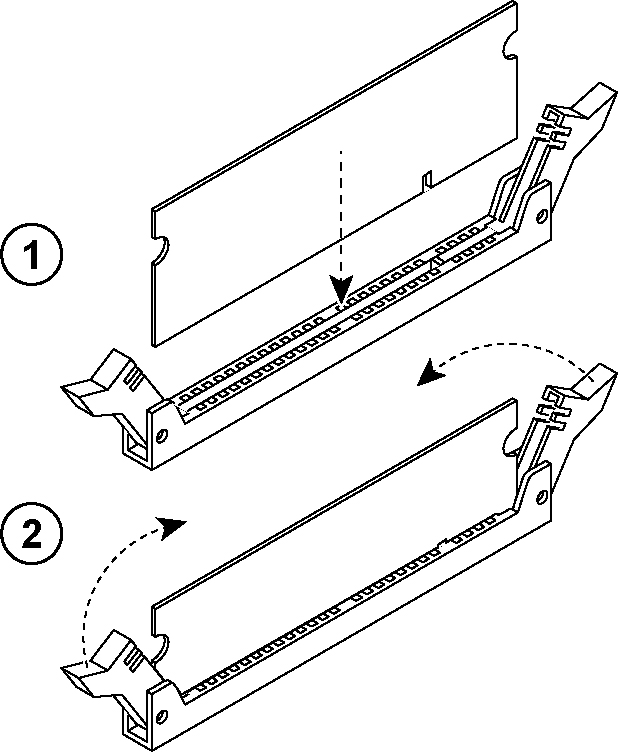
9. Press down on the memory module with your thumbs until you hear it click.
10. Ensure that all ejector tabs are in the upright locked position.
11. If necessary, replace the PCIe carrier.
12. Reinstall the cooling shroud.
13. Reinstall the chassis cover.
14. Reinstall the power cords and peripherals.
15. Power on the appliance.
Replacing memory modules in 2U SteelFusion Edge appliances
This section describes how to replace memory modules in the SteelFusion Edge 3100, SteelFusion Edge 3200, and SteelFusion Edge 5100 appliances. When replacing memory in the appliances, install the memory in the same slots.
The following diagram illustrates memory module slot locations in these appliances. (See
Figure: Memory module slot locations in 2U SteelFusion Edge appliances.)
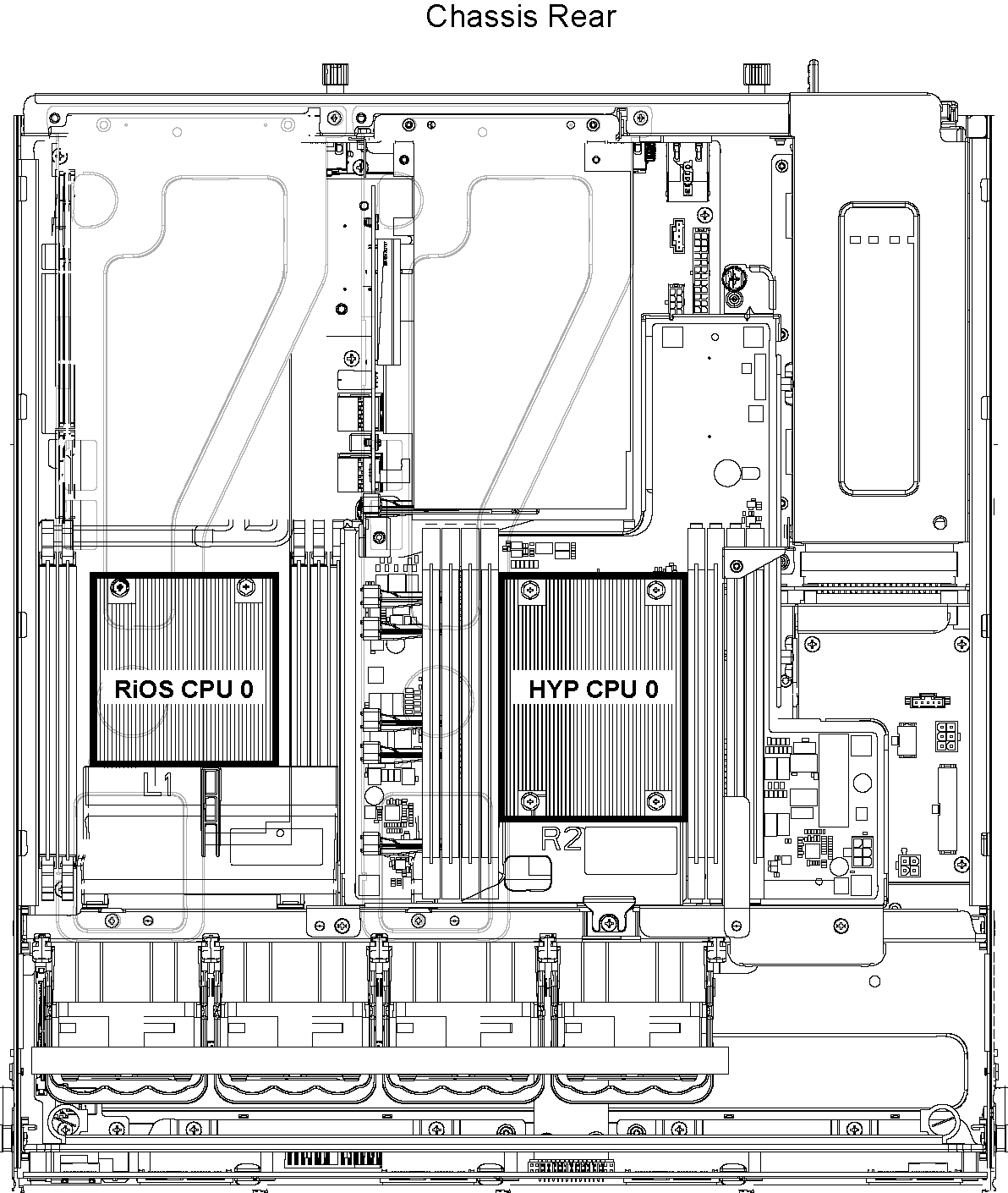
Figure: Memory module slot locations in 2U SteelFusion Edge appliances
To replace memory modules in a 2U SteelFusion Edge appliance
1. Power down the appliance.
2. Remove the chassis cover.
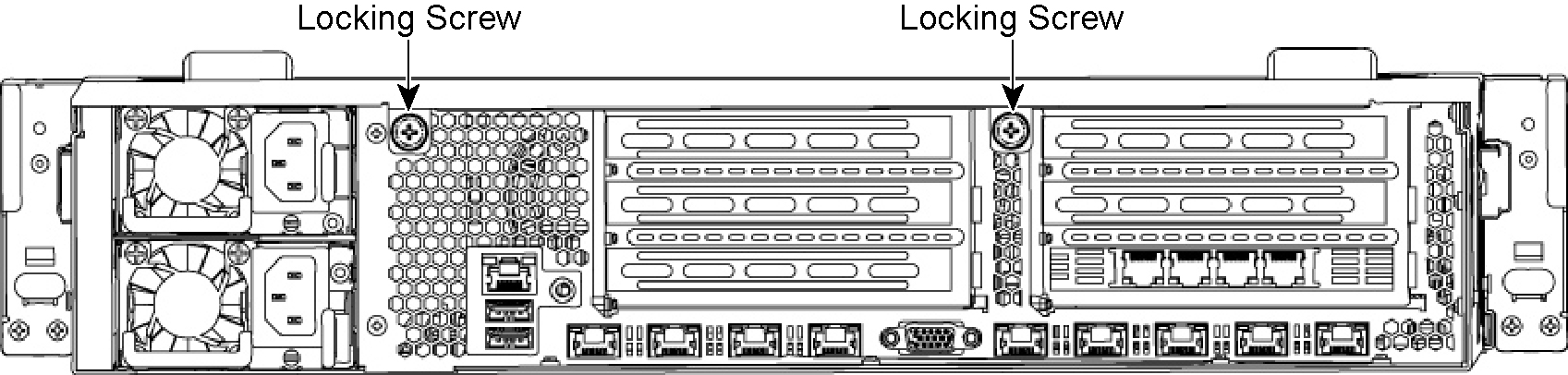
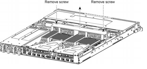
3. To release the PCIe carrier, remove the two locking screws on the top of the carrier (see
Figure: Locking screws) and the one locking screw on the rear panel.
Figure: Locking screws
Figure: Removing the PCIe carriers from the chassis
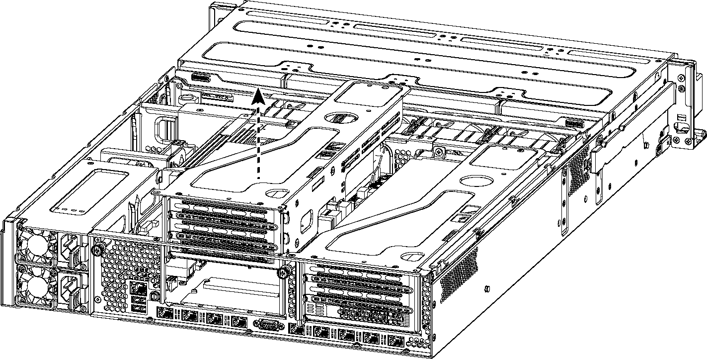
Figure: Removing cooling shroud
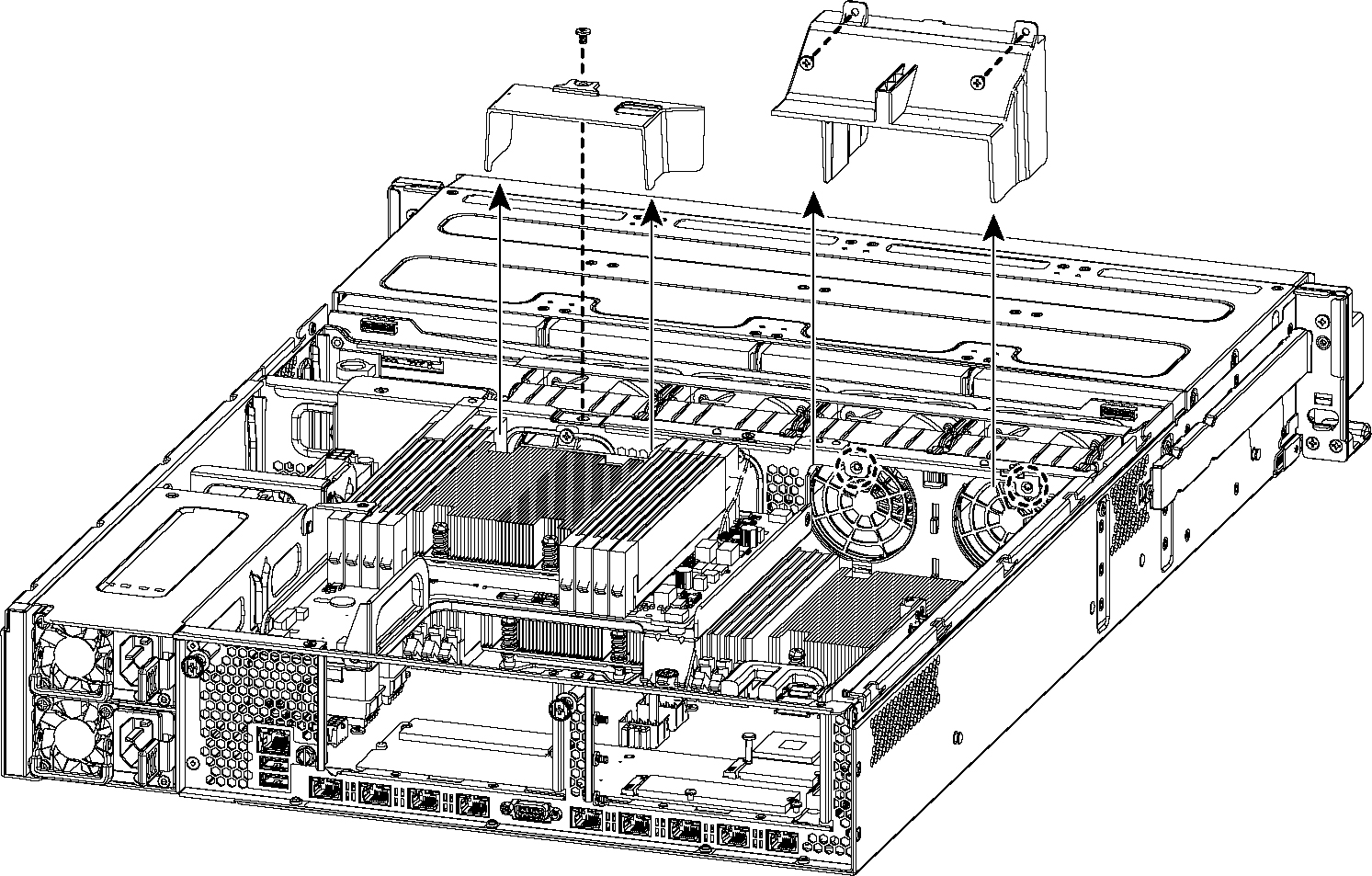
Caution: Be careful not to damage any surrounding components when removing and installing the cooling shroud. Lift the shroud straight up to avoid damaging any components of the appliance.
Figure: Accessing the memory modules
Figure: Proper handling of the memory module
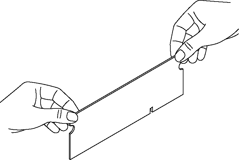
8. Remove the existing memory module and replace it with an approved memory module of the same size. When adding memory, always replace the memory in the black slots first. Make sure the memory is equally distributed on both sides.
Note: Replacing the existing memory module with a module of a different size is not recommended. Replace the failed memory module with the same memory module size. You must use approved memory modules. Contact Riverbed Support at https://support.riverbed.com to obtain the correct memory modules.
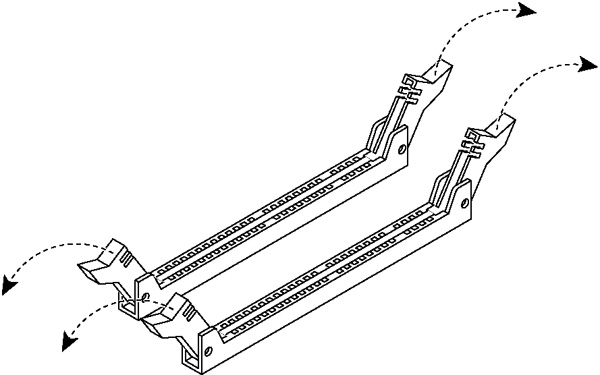
Figure: Inserting the memory modules into the connector slot and securing
10. Press down on the memory module with your thumbs while pulling up on the ejectors with your index fingers to lock the module into the slot.
11. Ensure that all ejector tabs are in the upright locked position.
12. Repeat
Step 6 to
Step 11 to install the remaining memory modules.
13. Reinstall the cooling shroud.
14. Reinstall the chassis cover.
15. Plug in the power cords and the peripherals.
16. Power on the appliance.
To replace memory modules in a 2U SteelFusion Edge appliance with the QPI module installed
1. Power down the appliance.
2. Remove the chassis cover.
3. To release the PCIe carrier, remove the two locking screws on the top of the carrier (see
Figure: Locking screws) and the one locking screw on the rear panel.
Figure: Locking screws
Figure: Removing the PCIe carriers from the chassis
Note: Use extreme care when removing the QPI module. Damage to the module can cause unexpected results.
5. Remove the two small cooling shrouds by flipping them up and off of the module.
6. Disconnect the power to the QPI module.
7. Unscrew the four screws on the QPI module. There are two on the top, one in the middle, and one at the bottom of the QPI module.
8. Carefully lift the QPI module up and remove it from the appliance.
Figure: Removing cooling shroud
Caution: Be careful not to damage any surrounding components when removing and installing the cooling shroud. Lift the shroud straight up to avoid damaging any components of the appliance.
Figure: Accessing the memory modules
Figure: Proper handling of the memory module
12. Remove the existing memory module and replace it with an approved memory module of the same size. When adding memory, always replace the memory in the black slots first. Make sure the memory is equally distributed on both sides.
Note: Replacing the existing memory module with a module of a different size is not recommended. Replace the failed memory module with the same memory module size. You must use approved memory modules. Contact Riverbed Support at https://support.riverbed.com to obtain the correct memory modules.
Figure: Inserting the memory modules into the connector slot and securing
14. Press down on the memory module with your thumbs while pulling up on the ejectors with your index fingers to lock the module into the slot.
15. Ensure that all ejector tabs are in the upright locked position.
16. Repeat
Step 6 to
Step 11 to install the remaining memory modules.
17. Reinstall the cooling shroud.
18. Reinstall the QPI module.
19. Connect the power wires for the QPI module.
20. Reinstall the small cooling shrouds.
21. Reinstall the chassis cover.
22. Plug in the power cords and the peripherals.
23. Power on the appliance.
Replacing fans
This section describes how to identify fan status and replace fans in the SteelFusion Edge appliances and includes the following procedures:
Note: You must power down the 1U SteelFusion Edge appliances prior to replacing fans.
Note: The 2U SteelFusion Edge appliances contain hot-swappable fans.
Determining fan status
This section describes how to determine the status of individual fans in the appliance.
To determine fan status
1. Connect to the CLI.
For details, see the Riverbed Command-Line Interface Reference Manual.
2. At the system prompt, enter the show stats fan command:
amnesiac # show stats fan
FanId RPM Min RPM Status
1 4700 100 ok
2 5700 100 ok
3 4700 100 ok
4 5800 100 ok
5 4700 100 ok
6 5700 100 ok
7 4900 100 ok
8 5900 100 ok
amnesiac #
The output and number of fans vary depending on your appliance.
Replacing fans in 1U SteelFusion Edge appliances
This section describes how to replace fans in the 1U SteelFusion Edge appliances. These appliances are equipped with six fans in a single casing. The fans are not hot swappable; you must power down the appliance before replacing the fans.
Note: You must use approved fans. To order fans, contact Riverbed Support at https://support.riverbed.com.
To replace the fans in the 1U SteelFusion Edge appliances
1. Remove the chassis cover.
2. Unplug the fan cables from the cable jacks on the motherboard.
3. Pull the fan unit up and out of the chassis. The fans are encased in one unit.
4. Seat the fan unit on the metal peg on the floor of the chassis.
5. Plug the cables of the replacement fan unit into the cable jacks.
6. Replace the chassis cover.
Note: If the RiOS IPMI alarm triggers when you open the chassis cover, run the clear hardware error-log command in the CLI to clear the alarm. For details, see the Riverbed Command-Line Interface Reference Manual.
Replacing fans in 2U SteelFusion Edge appliances
This section describes how to replace fans in the 2U SteelFusion Edge appliances. These appliances are equipped with four dual-unit hot-swappable fans at the front of the chassis.
Note: You must use approved fans. To order fans, contact Riverbed Support at https://support.riverbed.com.
To replace the fans in the 2U appliances
1. Remove the chassis cover.
2. Identify the faulty fan.
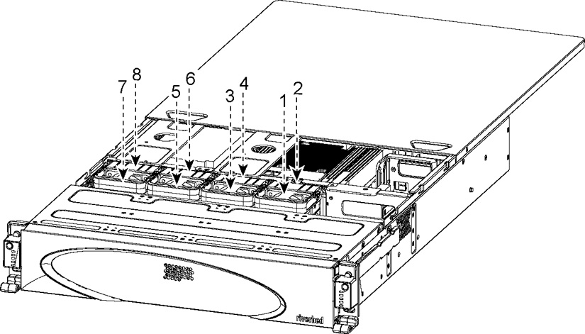
The appliance has four fan units, each with two fans.
Figure: Fan layout
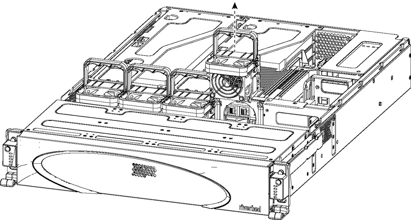
3. Pull the fan release lever upward and pull the fan up from the chassis.
Figure: Removing the fan
4. Plug the replacement fan into the chassis.
5. Replace the chassis cover.
Note: If the IPMI alarm triggers when you open the chassis cover, enter the clear hardware error-log command in the CLI to clear the alarm. For details, see the Riverbed Command-Line Interface Reference Manual.