Figure: CX5080 and CX7080 front panel with LEDs and buttons
Reference | LED/button | Description |
1 | Power On/Off Button and Integrated LED | On = Green (System is turned on.) Sleep State = Green (System is in S1 or S3 sleep state.) Off = No Light (Power is off.) |
2 | IPMI Warning LED | The IPMI Warning LED shows the current health of the server system. Normal = Green (No failures) Degraded/Warning = Amber (Indicates fan failure, high temperature, over voltage, or power supply failure.) Critical = Blinking Amber and Green (Indicates a problem that needs attention, such as optimization service down, no license, or in_path is not enabled for optimization service.) |
3 | ID LED | On = Blue (System identified remotely on the server.) Off = Off (System not identified.) |
4 | Reset Button | Press to reboot the appliance. |
5 | System ID Button | Press the system ID button when the system AC (Alternating Current) is on. The system ID LED indicates the system is identified with a blue light. Users from a remote site can activate the ID LED by inputting commands in IPMI. For details, contact Riverbed Support at https://support.riverbed.com. |
6, 7 | USB Ports v2.0 | |
8 | HDD/SSD LEDs | Activity LED (lower light) Link = Green (Drive present, with no activity.) Activity = Blinks Green (Drive present, with activity.) Status LED (upper light) Failed Disk = Solid Red |
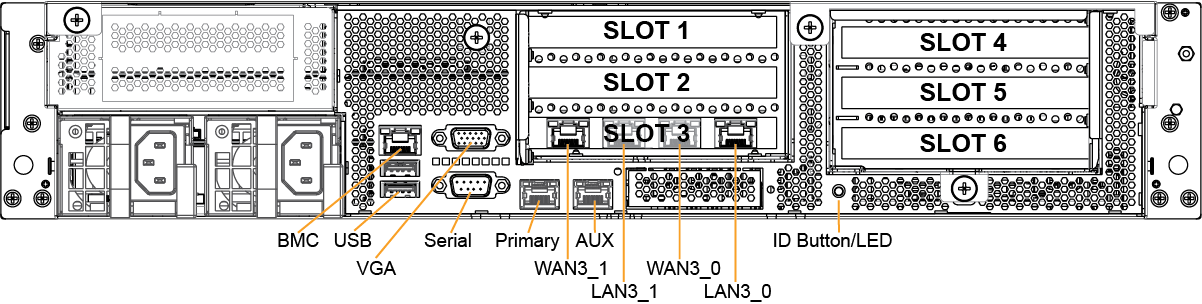
LED/button | Description |
ID LED/Button | On = Blue (System identified remotely on the server.) Off = Off (System not identified.) Press the system ID button when the system AC (Alternating Current) is on. The system ID LED indicates the system is identified with a blue light. Users from a remote site can activate the ID LED by inputting commands in IPMI. For details, contact Riverbed Support at https://support.riverbed.com. |
Primary and AUX Port LEDs | Left LED Link = Green Activity = Blinks Green No Link = Off Right LED 10 MBps = Off 100 MBps = Green 1000 MBps = Amber |
Four-Port 1 GbE Copper Bypass Card LEDs (preinstalled) | Link/Activity LED Link = Green Activity = Blinks Green Speed/Bypass/Disconnect LED 1000 MBps = Yellow 100 MBps = Green 10 MBps = Off Bypass = Blinks Green Disconnect = Blinks Yellow |
Power Supply LEDs | Power On and Healthy = Green Standby = Blinks Green Power Off = Off Power lost but second power supply has power = Amber Power on with warning = Blinks Amber (Indicates high temperature, high power, high current, or slow fan.) |
Specification | CX5080 | CX7080 |
Form factor | 2 U | 2 U |
Memory | 32 GB (4 x 8 GB) | B010 = 64 GB (8 x 8 GB) B020 = 96 GB (12 x 8 GB) B030 = 192 GB (12 x1 6 GB) |
HDD | 2 x 1 TB | 2 x 1 TB |
SSD | 6 x 240 GB | B010 = 6 x 480 GB B020 = 8 x 480 GB B030 = 8 x 960 GB |
Data store | 1.4 TB | B010 = 2.8 TB B020 = 3.8 TB B030 = 7.6 TB |
Dimensions (LxWxH) | 27.56 x 17.32 x 3.43 in. (700 x 440 x 87mm) | 27.56 x 17.32 x 3.43 in. (700 x 440 x 87mm) |
Weight (without packaging) | 51 lbs (23 kg) | 51 lbs (23 kg) |
Voltage | 100–127 V, 200-240 V | 100-127 V, 200-240 V |
PSU | 2 x 770 W 100-127 VAC/10A, 50/60 Hz 200-240 VAC/5A, 50/60 Hz | 2 x 770 W 100-127 VAC/10A, 50/60 Hz 200-240 VAC/5A, 50/60 Hz |
PCI slots | 6 | 6 |
Included bypass ports/max # ports | 4/20 | 4/20 |
System | CX 5080 | CX7080 | CX7080 | |||
Configuration | B010 | B010, B020 | B030 | |||
PSU type | 2 x 770 W | 2 x 770 W | 2 x 770 W | |||
AC input | 120 V | 230 V | 120 V | 230 V | 120 V | 230 V |
Max. amps. | 3.2 A | 1.7 A | 3.9 A | 2.0 A | 5.0 A | 2.6 A |
Max. watts | 372 W | 363 W | 467 W | 455 W | 598 W | 574 W |
Typical watts | 298 W | 290 W | 374 W | 364 W | 478 W | 459 W |
Max. volt-ampere | 383 VA | 395 VA | 477 VA | 473 VA | 604 VA | 592 VA |
Power factor | 97 W/VA | 92 W/VA | 98 W/VA | 96 W/VA | 99 W/VA | 97 W/VA |
BTU (typical) | 1015 BTU | 991 BTU | 1275 BTU | 1240 BTU | 1632 BTU | 1566 BTU |
Specification | CX5080 | CX7080 |
Operating acoustic | 56 dB (typical) | 56 dB (typical) |
Temperature (operating) | 32°- 104°F (0°- 40°C) | 32°- 104°F (0°- 40°C) |
Temperature (storage) | -40°- 140°F (-40°- 60°C) | 40°- 140°F (-40°- 60°C) |
Relative humidity | 40% - 90%, noncondensing at 40°C | 40% - 90%, noncondensing at 40°C |