Figure: CX3070 front panel with LEDs and buttons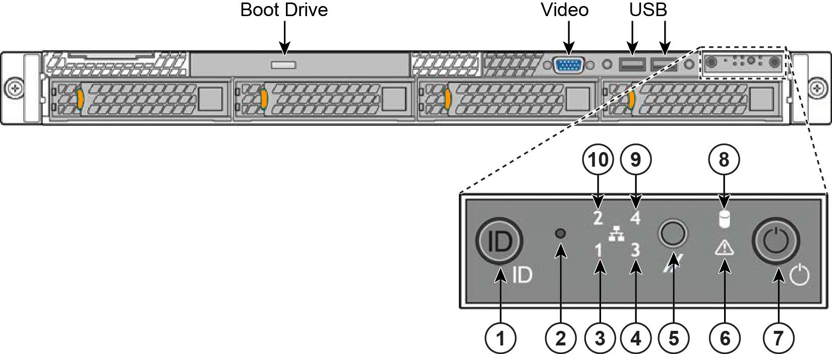
Reference | LED/button | Description |
1 | System ID Button with Integrated LED | Maintenance = Blue Toggles the integrated ID LED and the blue server board ID LED on and off. The System ID LED identifies the system for maintenance when installed in a rack of similar server systems. You can also remotely turn on and turn off the System ID LED using the IPMI “Chassis Identify” command which causes the LED to blink for 15 seconds. A duplicate System ID LED is on the back of the appliance to the left of the video port. |
2 | NMI Button | Pressing the NMI button puts the appliance in a halt state and issues a non-maskable interrupt (NMI). This helps when performing diagnostics for a given issue where a memory download is necessary to determine the cause of the problem. To prevent an inadvertent system halt, the NMI button is located behind the Front Control Panel faceplate and is only accessible with the use of a small tipped tool such as a pin or paper clip. |
3 10 | Network Activity LED Primary Auxiliary | Link = Green Activity = Blinks Green. The blink rate is consistent with the amount of network activity. The appliance doesn’t use the LEDs 4 and 9 shown in Figure: CX5070 and CX7070 front panel with LEDs and buttons. |
5 | System Cold Reset Button | Pressing this button reboots the appliance. |
6 | System Status LED | The System Status LED shows the current health of the server system. Healthy = Green Degraded = Yellow Critical = Blinks Yellow A duplicate System ID LED is on the back of the appliance to the right of the AUX port. |
7 | Power Button with Integrated LED | System On = Green System Off = No Light |
8 | Drive Activity | Activity = Blinks Green |
LEDs on Disk Drives | Activity LED Read/Write Activity = Blinks Green Disk Fault LED Failed Disk = Orange RAID Rebuild = Blinks Orange | |
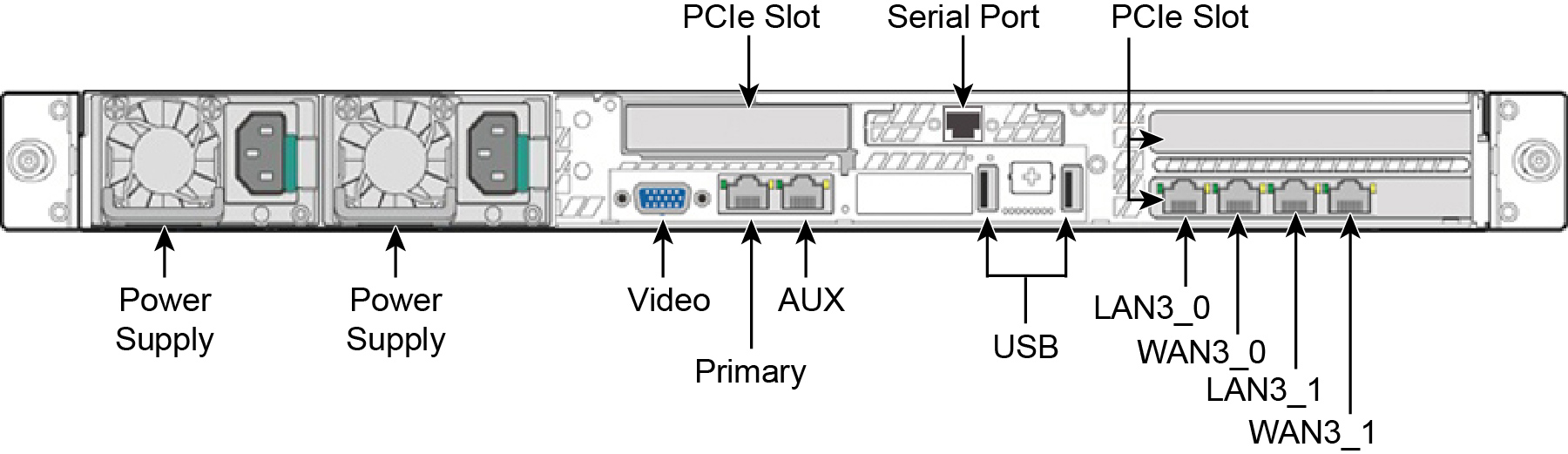
LEDs on Primary and AUX Ports | Left LED Link = Green Activity = Blinks Green Right LED 10 MBps data rate = No Light (with link on left LED) 100 MBps data rate = Green 1000 MBps data rate = Yellow | |
LEDs on Default 4 Port Copper Bypass Card | Link/Activity LED Link = Green Activity = Blinks Green Speed/Bypass/Disconnect LED 1000Mbit/s = Yellow 100Mbit/s = Green 10Mbit/s = Off Bypass = Blinks Green Disconnect = Blinks Yellow 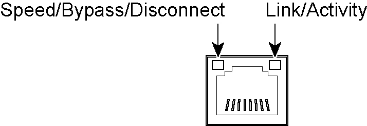 | |
LEDs on Power Supply | Power On and Healthy = Green Power Off = Off Standby = Blinks Green Power Lost But Second Power Supply Has Power = Amber Power On With Warning Events (high temperature, high power, high current, slow fan) = Blinks Amber |
CX3070 L/M/H | |
Form factor | 1U |
Hard disk | 2 x 1000 GB, 2 SSD x 160 |
Data store | 320 GB SSD |
Dimensions (LxWxH) | 25.21 x 17.24 x 1.7 in 640.4 x 438 x 43.2 mm |
Weight (without packaging) | 27 lbs / 12.2 kg |
Voltage frequency | 100-127V, 200-240V |
PSU | 2 x 450 W 100-127VAC/8A, 50/60Hz 200-240VAC/4A, 50/60Hz |
PCI slots | 3 |
Included bypass ports/max # ports | 4/12 |
System | CX3070 | CX3070 |
Configuration | All (L/M/H) | All (L/M/H) |
PSU type | 2 x 450W | 2 x 450W |
AC input | 120V | 230V |
Max. amps. | 1.54 | .76 |
Max. watts | 152.8 | 145.4 |
Typical watts | 122 | 116 |
Max VA | 154 | 147 |
Power factor | 98.96 | 99.16 |
BTU (typical) | 417 | 397 |
Specification | Description |
Operating acoustic | 7.0 BA sound power (Typical) 52 dBa sound pressure |
Temperature (operating) | 10° - 35° C 50° - 95 F |
Temperature (storage) | -40°- 70°C -40° - 158° F |
Relative humidity | 50% to 90%, non-condensing with a maximum wet bulb of 28° C (at temperatures from 25° to 35° C) |
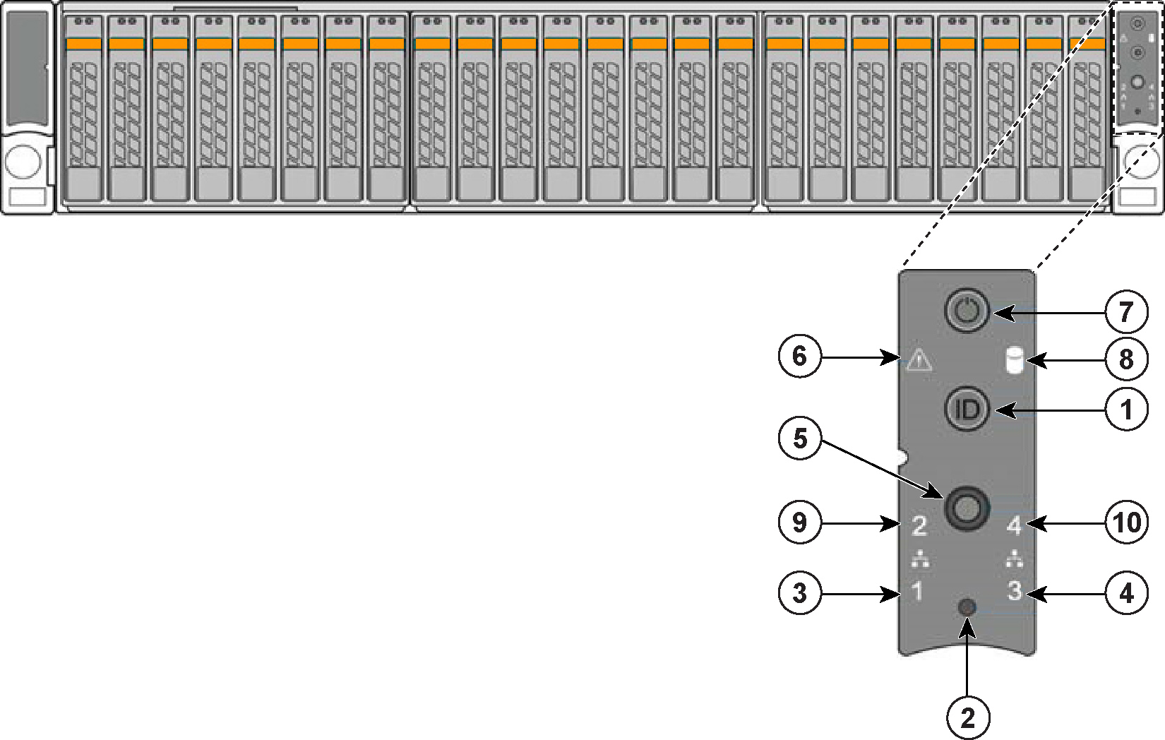

Reference | LED/button | Description |
1 | System ID Button with Integrated LED | Maintenance = Blue Toggles the integrated ID LED and the blue server board ID LED on and off. The System ID LED identifies the system for maintenance when installed in a rack of similar server systems. You can also remotely turn on and turn off the System ID LED using the IPMI “Chassis Identify” command which causes the LED to blink for 15 seconds. A duplicate System ID LED is on the back of the appliance to the left of the video port. |
2 | NMI Button | Pressing the NMI button puts the appliance in a halt state and issues a non-maskable interrupt (NMI). This helps when performing diagnostics for a given issue where a memory download is necessary to determine the cause of the problem. To prevent an inadvertent system halt, the NMI button is located behind the Front Control Panel faceplate and is only accessible with the use of a small tipped tool such as a pin or paper clip. |
3 10 | Network Activity LED Primary Auxiliary | Link = Green Activity = Blinks Green. The blink rate is consistent with the amount of network activity. The appliance doesn’t use the LEDs 4 and 9 shown in Figure: CX5070 and CX7070 front panel with LEDs and buttons. |
5 | System Cold Reset Button | Pressing this button reboots the appliance. |
6 | System Status LED | The System Status LED shows the current health of the server system. Healthy = Green Degraded = Yellow Critical = Blinks Yellow |
7 | Power Button with Integrated LED | System On = Green System Off = No Light |
8 | Drive Activity | Activity = Blinks Green |
LEDs on Disk Drives | Activity LED Read/Write Activity = Blinks Green Disk Fault LED Failed Disk = Orange RAID Rebuild = Blinks Orange | |
LEDs on Primary and AUX Ports | Left LED Link = Green Activity = Blinks Green Right LED 10 MB/sec data rate = No Light (with link on left LED) 100 MB/sec data rate = Green 1000 MB/sec data rate = Yellow | |
LEDs on Default 4 Port Copper Bypass Card | Link/Activity LED Link = Green Activity = Blinks Green Speed/Bypass/Disconnect LED 1000Mbit/s = Yellow 100Mbit/s = Green 10Mbit/s = Off Bypass = Blinks Green Disconnect = Blinks Yellow | |
LEDs on Power Supply | Power On and Healthy = Green Power Off = Off Standby = Blinks Green Power Lost But Second Power Supply Has Power = Amber Power On With Warning Events (high temperature, high power, high current, slow fan) = Blinks Amber |
CX5070 M/H | CX7070 L | CX7070 M | CX7070 H | |
Form factor | 2 U | 2 U | 2 U | 2 U |
Hard disk/SSD | 2 x 1000 GB HDD 6 x 160GB SSDs | 2 x 1000 GB HDD 6 x 300 GB SSDs | 2 x 1000 GB HDD 8 x 300 GB SSD | 2 x 1000 GB HDD 16 x 300 GB SSD |
Data Store | 960 GB SSD | 1.8 TB SSD | 2.4 TB SSD | 4.8 TB SSD |
Dimensions (LxWxH) | 27.87 x 17.24 x 3.45 in 707.8 x 438 x 87.6 mm | 27.87 x 17.24 x 3.45 in 707.8 x 438 x 87.6 mm | 27.87 x 17.24 x 3.45 in 707.8 x 438 x 87.6 mm | 27.87 x 17.24 x 3.45 in 707.8 x 438 x 87.6 mm |
Weight (without packaging) | 41 lbs/18.6 kg | 41 lbs/18.6 kg | 41 lbs/18.6 kg | 42 lbs/19.05 kg |
Voltage frequency | 100-127V, 200-240V | 100-127V, 200-240V | 100-127V, 200-240V | 100-127V, 200-240V |
PSU | 2 x 770W 100-127VAC/8.2A, 50/60Hz 200-240VAC/4.4A, 50/60Hz | 2 x 770W 100-127VAC/8.2A, 50/60Hz 200-240VAC/4.4A, 50/60Hz | 2 x 770W 100-127VAC/8.2A, 50/60Hz 200-240VAC/4.4A, 50/60Hz | 2 x 770W 100-127VAC/8.2A, 50/60Hz 200-240VAC/4.4A, 50/60Hz |
PCI slots | 6 | 6 | 6 | 6 |
Included bypass ports/max # ports | 4/20 | 4/20 | 4/20 | 4/20 |
System | CX5070 | CX7070 | ||
Configuration | All (M/H) | All (L/M/H) | ||
PSU type | 2 x 770W | 2 x 770W | ||
AC input | 120V | 230V | 120V | 230V |
Max. amps. | 3.0 | 1.5 | 5.3 | 2.7 |
Max. watts | 298 | 291 | 527 | 520 |
Typical watts | 238 | 232 | 422 | 416 |
Max VA | 301 | 293 | 533 | 524 |
Power factor | 98.96 | 99.16 | 98.96 | 99.16 |
BTU (typical) | 814 | 794 | 1439 | 1418 |
CX5070 | CX7070 | |
Operating acoustic | 7.0 BA sound power (Typical) 55 dBa sound pressure | 7.0 BA sound power (Typical) 55 dBa sound pressure |
Temperature (operating) | 10° - 35° C 50° - 95 F | 10° - 35° C 50° - 95 F |
Temperature (storage) | -40° - 70° C -40° - 158° F | -40° - 70° C -40° - 158° F |
Relative humidity | 50% to 90%, noncondensing with a maximum wet bulb of 28° C (at temperatures from 25° to 35° C) | 50% to 90%, noncondensing with a maximum wet bulb of 28° C (at temperatures from 25° to 35° C) |