LAN Topologies
This topic explains how to configure the LAN side of the SteelConnect gateway. It includes these possible deployment scenarios:
This list of possible scenarios highlights some of the most common deployments, but is not an exhaustive list.
To learn more about how to create and configure sites and VLANS (zones) for your topology, see the SteelConnect Manager User Guide.
Spanning tree on LAN ports
Spanning Tree Protocol (STP) is a Layer 2 protocol that passes data back and forth to find out how the switches and gateways are organized on the network and uses this information to create a logical spanning tree. Each site configures a different spanning tree.
STP is active by default on the SteelConnect gateway LAN ports and it prevents network malfunction by blocking ports that cause loops in redundant network paths.
SDI-1030 and VGW on ESX do not support Spanning Tree.
STP is disabled on branch gateways configured for high availability. Due to the lack of STP, we recommend attaching only one switch to one gateway and avoiding mesh topologies with HA deployments.
The original version of Spanning Tree IEEE 802.1D takes between 30 to 50 seconds to converge in a network. Rapid Spanning Tree Protocol (RSTP) defined in 802.1w is an enhanced version with convergence time of 6 seconds (3x2 hello interval or even lower).
SteelConnect gateways and switches implement Multiple Spanning Tree (MST) protocol defined in IEEE 802.1s. MST uses the best features of PVST+ and RSTP, and MST can run a single instance of Spanning Tree Protocol for a group of VLANs. So in a network of 1000 VLANs you can group the first 500 VLANs into MST group 1 and the last 500 VLANs in MST group 2 and reduce 1000 VLAN instances in RPVST+ to just two logical instances.
All spanning tree operations include these four primary steps:
1. Determining a root bridge.
2. Selecting a root port.
3. Selecting designated ports.
4. Blocking ports with loops.
The election of a root bridge is the most crucial step and dictates the movement of Layer 2 traffic. A device with the lowest bridge priority becomes a root bridge in the network. If there is a tie with bridge priority, then the device with lowest MAC address becomes the root bridge. Unlike other vendors, we do not employ default bridge priority of 32768 because SteelConnect access points have the lowest MAC addresses of all Riverbed products.
All SteelConnect devices start with MAC address 6C:98:EB.
The following are the default priorities:
•SDI-S48 - 12288
•SDI-S24 - 16384
•SDI-S12 - 20480
•SDI-330 - 24576
•SDI-130 - 28672
•SDI-AP5/5r - 36864
•SDI-AP3 - 40960
Although access points currently have higher priority, do not change the value or decrease the default priority, which would result in access points becoming a root bridge in your network.
For example, if you have a combination of S48 and S24 switches and a gateway, then the S48 switch will assume the role of root bridge.
When SteelConnect appliances are deployed in a multivendor environment where a root bridge is already elected, we recommend using Root Guard, BPDU Guard, or Loop Guard features or reducing the existing root bridge priority to less than 12288 to avoid or reduce downtime.
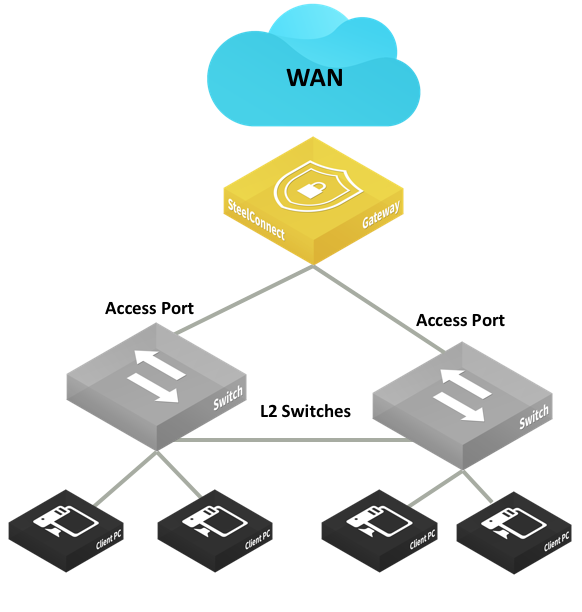
Layer 2: Access port
This deployment features switches with access port connections configured in a single zone.
This topology can have a SteelConnect gateway acting as a switch, a single switch, or a pair of switches.
Layer 2 deployment with access port connection
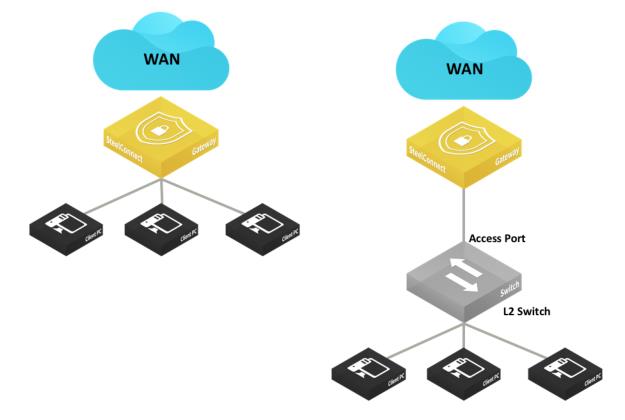
Layer 2 deployments with dual switches and access port connections
In these topologies, Spanning Tree is active by default on the SteelConnect gateway LAN ports and prevents network malfunction by blocking ports that cause loops.
In this topology, you configure the switch uplink port as an access port.
The following SteelConnect gateways support this topology.
SDI-VGW | SDI-130/130W | SDI-330 | SDI-1030 | SDI-5030 |
| | | | |
You can deploy the SteelConnect virtual gateway (SDI-VGW) on a universal customer premises equipment (uCPE) or a Riverbed SteelFusion appliance as long as physical ports are attached to the ports of the virtual appliance.
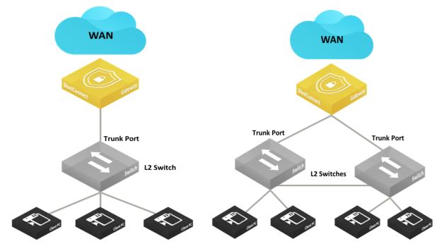
Layer 2: Trunk port
This deployment features switches with trunk port connections for multizone environments.
Layer 2 deployments with trunk port
The following SteelConnect gateways support this topology.
SDI-VGW | SDI-130/130W | SDI-330 | SDI-1030 | SDI-5030 |
| | | | |
This topology does not support native VLAN. All frames must be tagged, and untagged frames are ignored/dropped.
To configure the switch and SCM to support this topology
1. Physically connect the Layer 2 switch to a LAN port on the SteelConnect gateway.
2. Configure the connected port as a trunk/ 802.1q tagged port.
In SCM, choose Appliances > Ports, select a LAN port and select Multizone (VLAN tagged) from the drop-down Port mode menu.
LAN port mode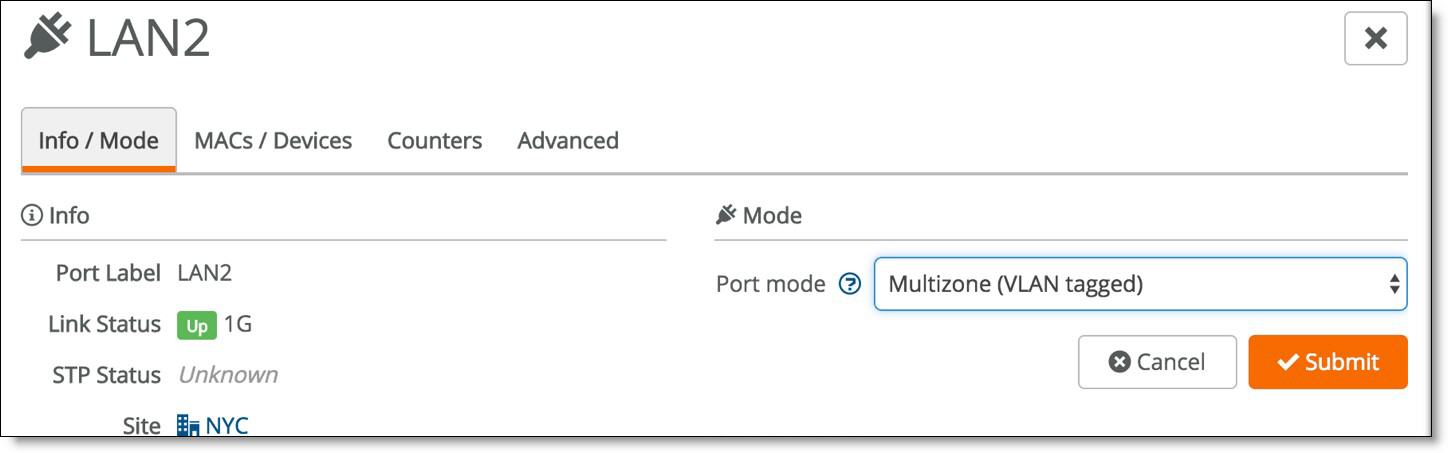
3. Configure the core switch with a trunk port to connect to the SteelConnect gateway.
Here is a sample configuration:
interface GigabitEthernet1/2
description ToSteelConnectGateway
switchport trunk encapsulation dot1q
switchport trunk allowed vlan all
switchport mode trunk
vlan dot1q tag native
Layer 2: High availability
High availability on the LAN provides network redundancy and reliability and maintains uninterrupted service in the event of a power, hardware, software, or WAN uplink failure. Gateways in an HA pair must be the same model.
LAN high-availability topology
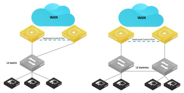
LAN high-availability topology shows the two supported configurations. The interconnections between the SteelConnect HA pair and the Layer 2 switch can be configured as access mode (singlezone) or trunk/802.1q (multizone).
The Spanning Tree Protocol (STP) is disabled on branch gateways configured for high availability. Without STP, we recommend you attach only one switch to a gateway and avoid mesh topologies.
The HA pair uses the Dedicated Control Port to communicate with each other, and that port serves as the VRRP link between the two gateways.
To avoid traffic loops, do not use the dedicated control port to transmit data.
For model SDI-1030 gateways, one port must be configured as the Dedicated Control Port by assigning the Control Port role.
Setting the Control Port
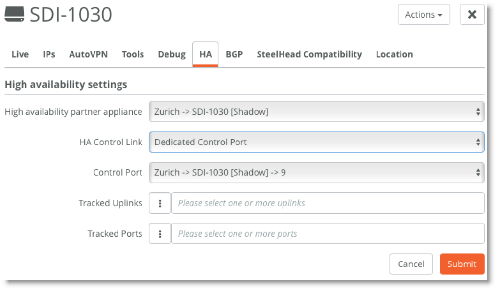
You can use tracked ports to trigger failover if the network goes down on the LAN side of the gateway (for example, if a switch fails) to avoid a black hole situation.
The following SteelConnect gateways support this topology.
SDI-VGW | SDI-130/130W | SDI-330 | SDI-1030 | SDI-5030 |
| | | | |
Layer 3: Switch behind a SteelConnect gateway with static routing
A typical use case for Enterprise networks uses a core Layer 3 switch (or a pair of switches) handling inter-VLAN routing for the local network.
LAN topology with Layer 3 switch behind SteelConnect gateway with static routin
g
You can configure static routes:
•on the core switches to route traffic to the WAN through the SteelConnect gateway.
•on the SteelConnect gateway to identify the local subnets and be able to advertise them on the WAN.
The IP addresses and subnets are examples only. You can configure addresses appropriate for your network.
The following SteelConnect gateways support this topology.
SDI-VGW | SDI-130/130W | SDI-330 | SDI-1030 | SDI-5030 |
| | | | |
To configure the switch and SCM to support this topology
1. Create a zone for the LAN interconnection or update the default LAN zone assigned to the site.
Creating a zone
2. Physically connect the Layer 2 switch to a LAN port on the SteelConnect gateway.
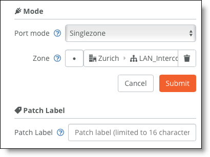
3. For the newly configured zone, configure the connected port under Port mode to be Singlezone.
Setting the port mode
4. Configure the switch port.
Here is a sample configuration:
Switch(config)# interface giga 0/1
Switch(config-if)# no switchport
Switch(config-if)# ip address 172.16.20.1 255.255.255.248
Switch(config-if)# no shutdown
Switch(config)# ip route 0.0.0.0 0.0.0.0 172.16.20.2
5. Test the connectivity between the two devices.
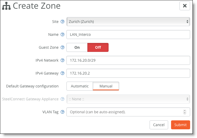
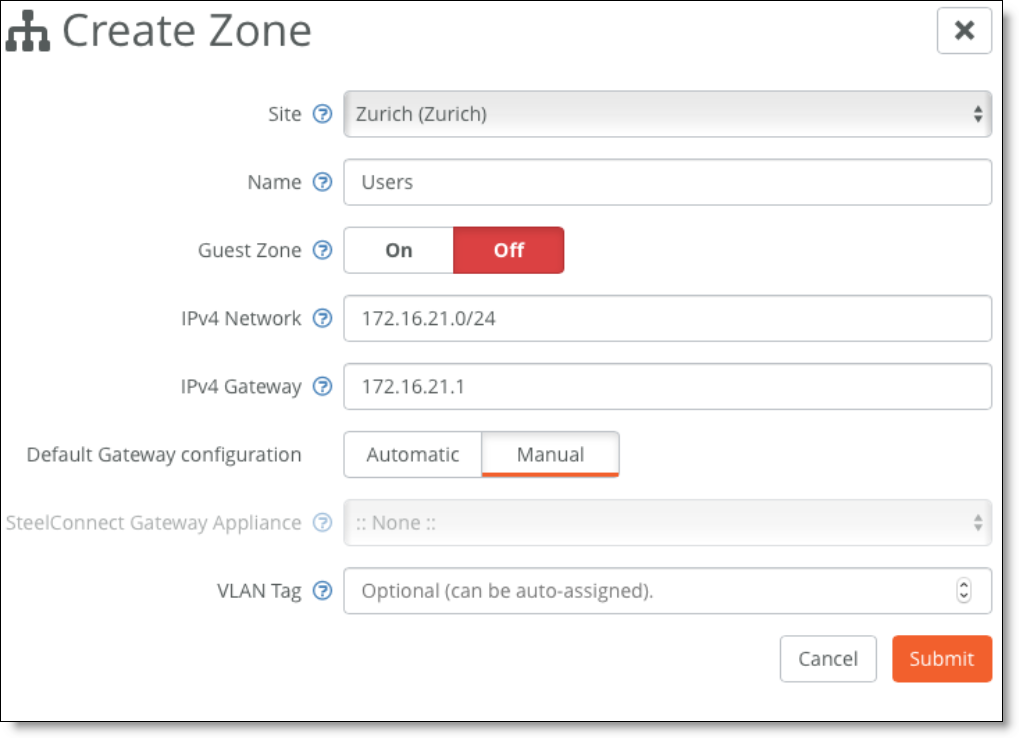
6. On SCM, for each local subnet, create a zone with a manual default gateway configuration.
Creating a zone with a manual default gateway configuration
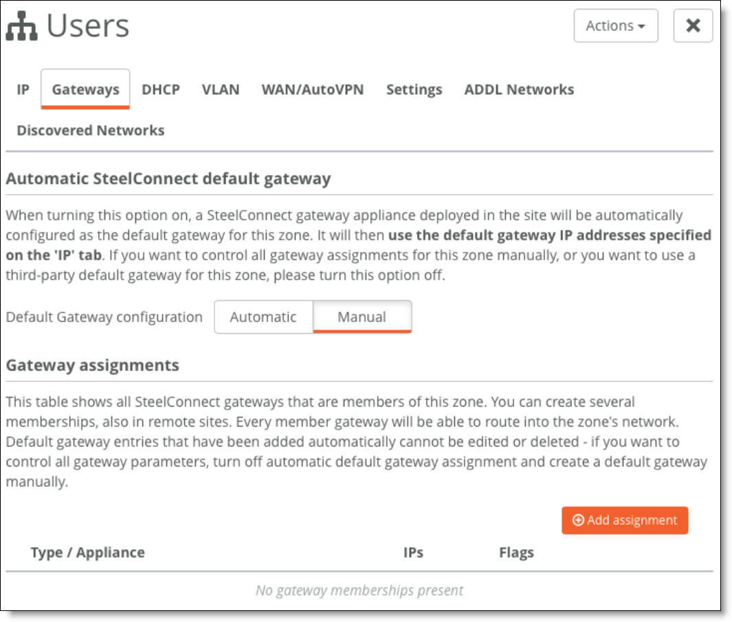
7. For the newly created zones, edit the configuration under the Gateways tab and delete the Gateway assignment.
Deleting the gateway assignment
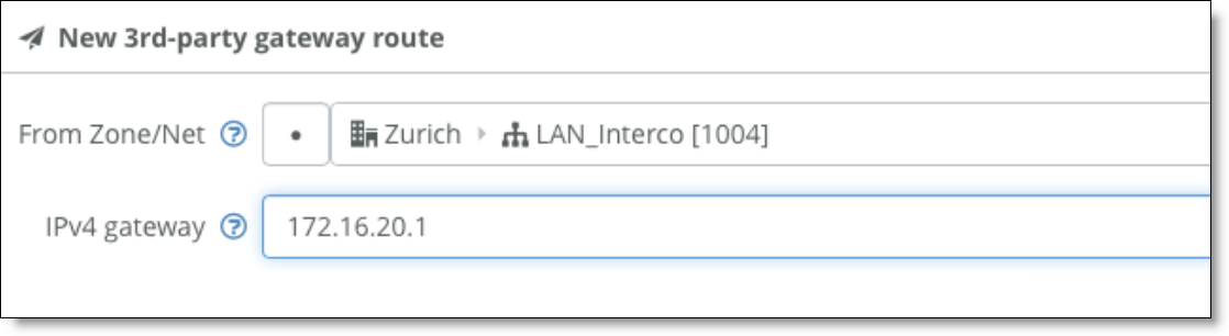
8. Select the Settings tab and create a third-party route for the gateway to reach the VLANs through the core switch.
3rd-party gateway route
Layer 3: Switch behind a SteelConnect gateway with LAN-side OSPF
An alternative to the previous configuration is to leverage dynamic routing protocols such as OSPF to discover subnets behind a Layer 3 switch.
LAN topology with Layer 3 switch behind SteelConnect gateway with dynamic routin
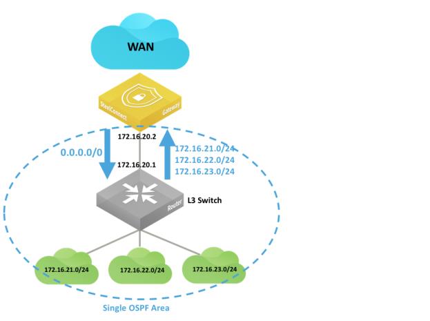
g
In this deployment, you must configure OSPF on the Layer 3 switch as well as on the SteelConnect Manager so that:
•the switch advertises the LAN subnets to the SteelConnect gateway.
•the SteelConnect gateway can learn the LAN subnets and eventually redistribute them on the WAN side as well as making SteelConnect Manager aware of those subnets in that site.
•by default, the gateway advertises a default route to the Layer 3 switch.
The following SteelConnect gateways support this topology.
SDI-VGW | SDI-130/130W | SDI-330 | SDI-1030 | SDI-5030 |
| | | | |
To configure SCM to support this topology
1. Create a zone for the LAN interconnection, or update the default LAN zone assigned to the site.
Creating a zone
2. Physically connect the Layer 2 switch to a LAN port on the SteelConnect gateway.
3. For the newly configured zone, set the connected port under Port mode to be Singlezone.
Setting the port mode
4. Configure the switch port accordingly.
Here is a sample configuration:
Switch(config)# interface giga 0/1
Switch(config-if)# no switchport
Switch(config-if)# ip address 172.16.20.1 255.255.255.248
Switch(config-if)# no shutdown
router ospf 1
network 172.16.21.0 0.0.0.255 area 0
network 172.16.22.0 0.0.0.255 area 0
network 172.16.23.0 0.0.0.255 area 0
5. Test connectivity between the two devices.
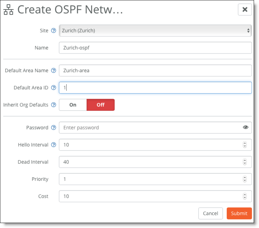
6. On SCM, choose Routing > OSPF and create a new OSPF network for the site.
Creating an OSPF network
7. Attach the interface to learn the routes.
In this example, the LAN_Interco Zone.
Attach the interface to learn the routes
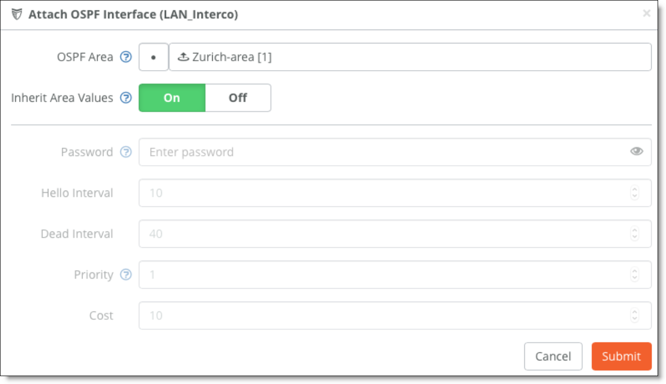
The SteelConnect gateway connects to its OSPF peer, in this case the Layer 3 switch on the LAN side, and starts discovering the LAN subnets.
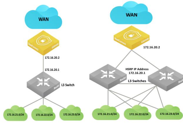
Layer 3: High availability
Configure the HA pair and the pair’s connection to the Layer 3 switch or router in the same way you would for a Layer 2 topology. See
Layer 2: High availability.
High-availability pair of gateways connected to a single Layer 3 switch or router
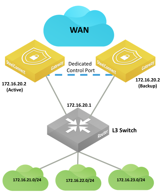
High-availability pair of gateways connected to two Layer 3 switches or routers
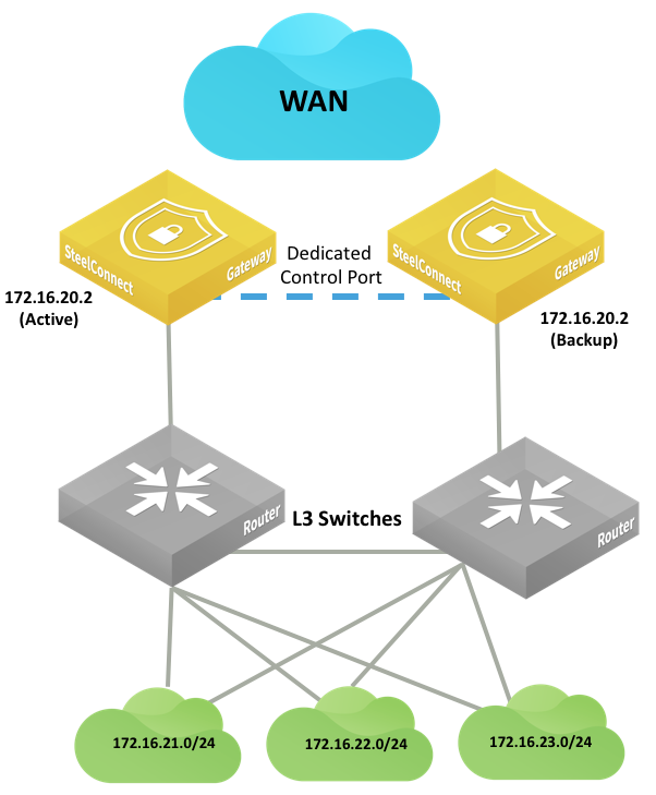
The following SteelConnect gateways support these topologies.
SDI-VGW | SDI-130/130W | SDI-330 | SDI-1030 | SDI-5030 |
| | | | |
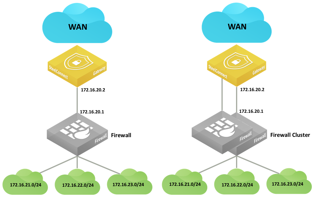
Integration with firewalls
LAN-side integration with firewalls is very similar to LAN topologies with Layer 3 switches. You can configure static routes or dynamic routing to reach subnets behind the firewalls.
LAN topologies with firewalls
HA LAN topologies with firewalls
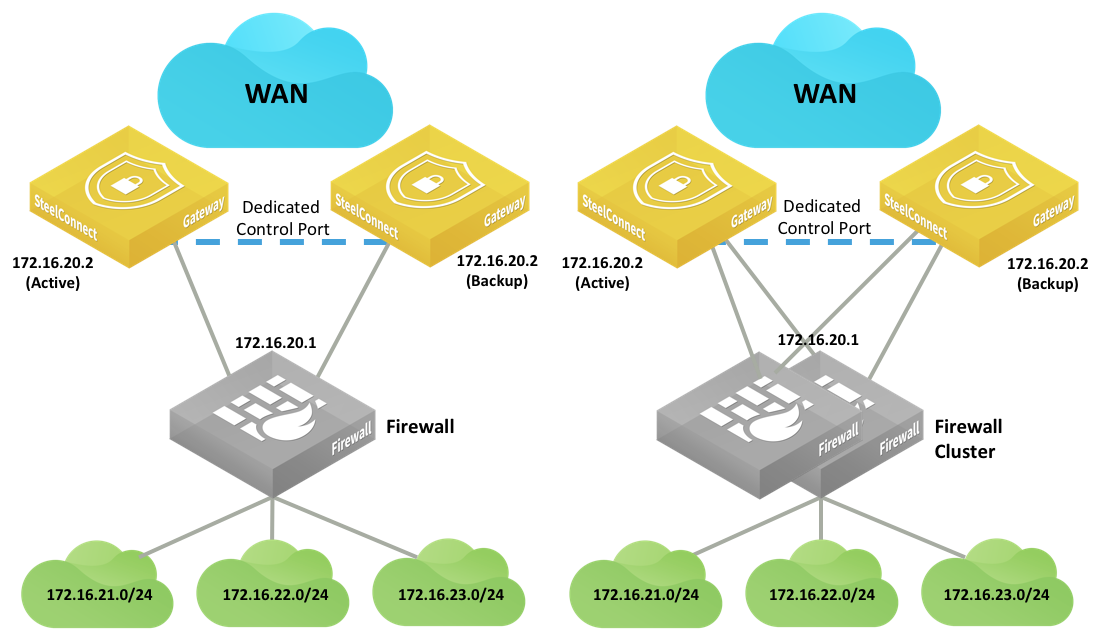
If the firewall applies NAT-to-LAN traffic, the SteelConnect gateway only sees the firewall IP address, so there is no need to configure static routes or OSPF on the LAN side.
Double NAT can cause issues with some application traffic. You can configure gateway uplinks to skip outbound NAT to resolve double NAT issues.
Firewall clusters typically operate in active/passive mode. Each appliance has the same configuration, and if one goes down the other activates and resumes operation with the same IP addresses. The gateways do not detect a traffic loop.
Integration with Riverbed SteelHead
You can deploy SteelConnect gateways with SteelHeads for WAN optimization.
SteelHead topologies
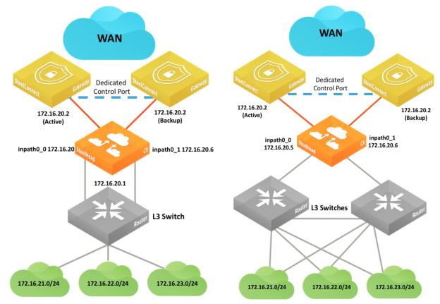
Another SteelHead topology
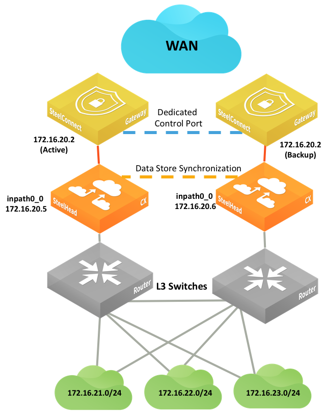
By default, SteelConnect appliances have the SteelHead compatibility feature on.
To enable SteelConnect compatibility on a SteelHead CX, enter this Riverbed command-line interface (CLI) command: steelhead steel-connect compatibility enable
See the SteelConnect Manager User Guide for more information about compatibility.
See the SteelHead Deployment Guide and SteelHead User Guide for more details about the SteelHead appliance configuration and deployment options.