SteelHead Interceptor 9600 front panel with LEDs and buttons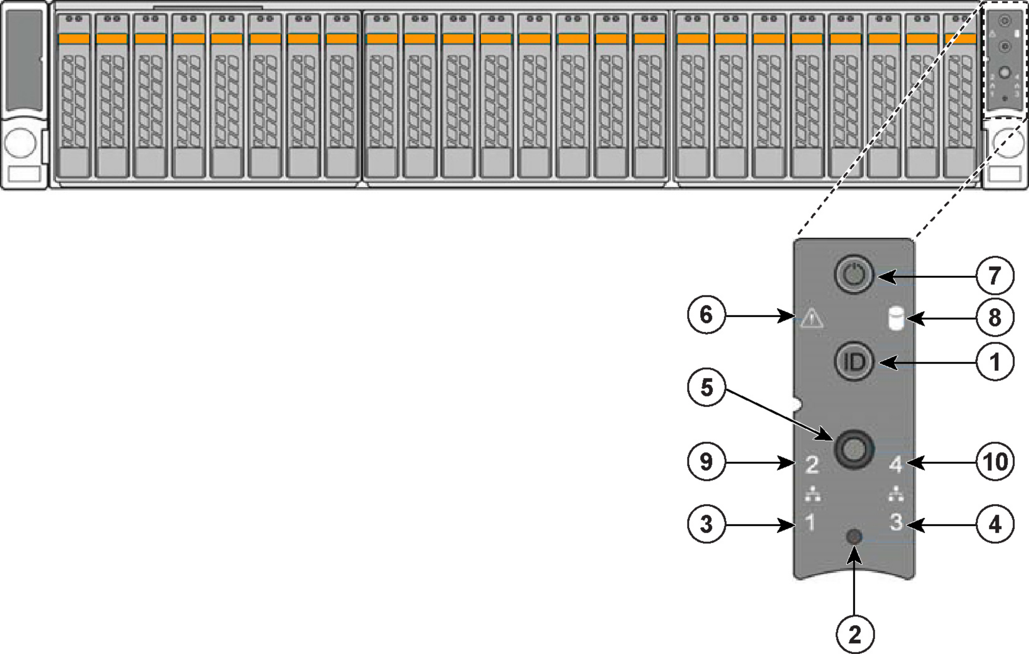
Reference | LED/button | Description |
1 | System ID Button with Integrated LED | Maintenance = Blue Toggles the integrated ID LED and the blue server board ID LED on and off. The System ID LED identifies the system for maintenance when installed in a rack of similar server systems. You can also remotely turn on and turn off the System ID LED using the Intelligent Platform Management Interface (IPMI) ipmitool chassis identify command, which causes the LED to blink for 15 seconds. A duplicate System ID LED is on the back of the appliance to the left of the video port. |
2 | NMI Button | Pressing the NMI button puts the appliance in a halt state and issues a nonmaskable interrupt (NMI). This helps when performing diagnostics for a given issue where a memory download is necessary to determine the cause of the problem. To prevent an inadvertent system halt, the NMI button is located behind the Front Control Panel faceplate and is only accessible with the use of a small tipped tool such as a pin or paper clip. |
3 10 | Network Activity LED Primary Auxiliary | Link = Green Activity = Blinks green. The blink rate is consistent with the amount of network activity. The appliance doesn’t use the LEDs 4 and 9 shown in
Figure: SteelHead Interceptor 9600 front panel with LEDs and buttons. |
5 | System Cold Reset Button | Pressing this button reboots the appliance. |
6 | System Status LED | The System Status LED shows the current health of the server system. Healthy = Green Degraded = Yellow Critical = Blinks yellow |
7 | Power Button with Integrated LED | System on = Green System off = No light |
8 | Drive Activity | Activity = Blinks green |
LEDs on Disk Drives | Activity LED Read/write activity = Blinks green Disk Fault LED Failed Disk = Orange RAID Rebuild = Blinks orange | |
LEDs on Primary and AUX Ports | Left LED Link = Green Activity = Blinks green Right LED 10 Mbps data rate = No light (with link on left LED) 100 Mbps data rate = Green 1000 Mbps data rate = Yellow | |
LEDs on Default Four-Port Copper Bypass Card | Link/Activity LED Link = Green Activity = Blinks green Speed/Bypass/Disconnect LED 1000 Mbps = Yellow 100 Mbps = Green 10 Mbps = Off Bypass = Blinks green Disconnect = Blinks yellow  | |
LEDs on Power Supply | Power on and healthy = Green Power off = Off Standby = Blinks green Power lost but second power supply has power = Amber Power on with warning events (high temperature, high power, high current, slow fan) = Blinks amber |
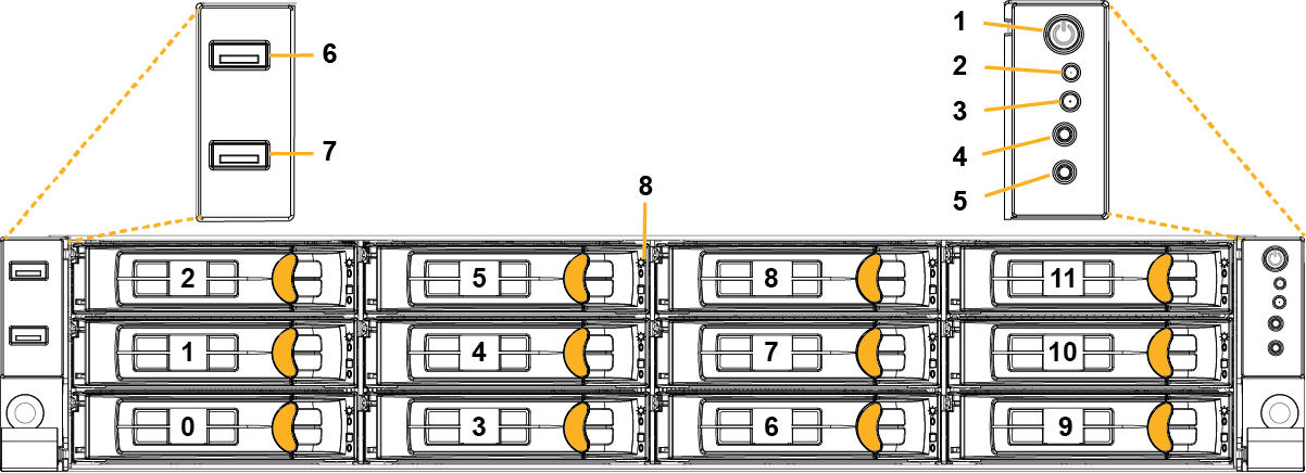
Reference | LED/button | Description |
1 | Power On/Off Button and Integrated LED | On = Green (System is turned on.) Sleep State = Green (System is in S1 or S3 sleep state.) Off = No Light (Power is off.) |
2 | IPMI Warning LED | The IPMI Warning LED shows the current health of the server system. Normal = Green (No failures) Degraded/Warning = Amber (Indicates fan failure, high temperature, over voltage, or power supply failure.) Critical = Blinking Amber and Green (Indicates a problem that needs attention, such as optimization service down, no license, or in_path is not enabled for optimization service.) |
3 | ID LED | On = Blue (System identified remotely on the server.) Off = Off (System not identified.) |
4 | Reset Button | Press to reboot the appliance. |
5 | System ID Button | Press the system ID button when the system AC (Alternating Current) is on. The system ID LED indicates the system is identified with a blue light. Users from a remote site can activate the ID LED by inputting commands in IPMI. For details, contact Riverbed Support at https://support.riverbed.com. |
6, 7 | USB Ports v2.0 | |
8 | HDD/SSD LEDs | Activity LED (lower light) Link = Green (Drive present, with no activity.) Activity = Blinks Green (Drive present, with activity.) Status LED (upper light) Failed Disk = Solid Red |
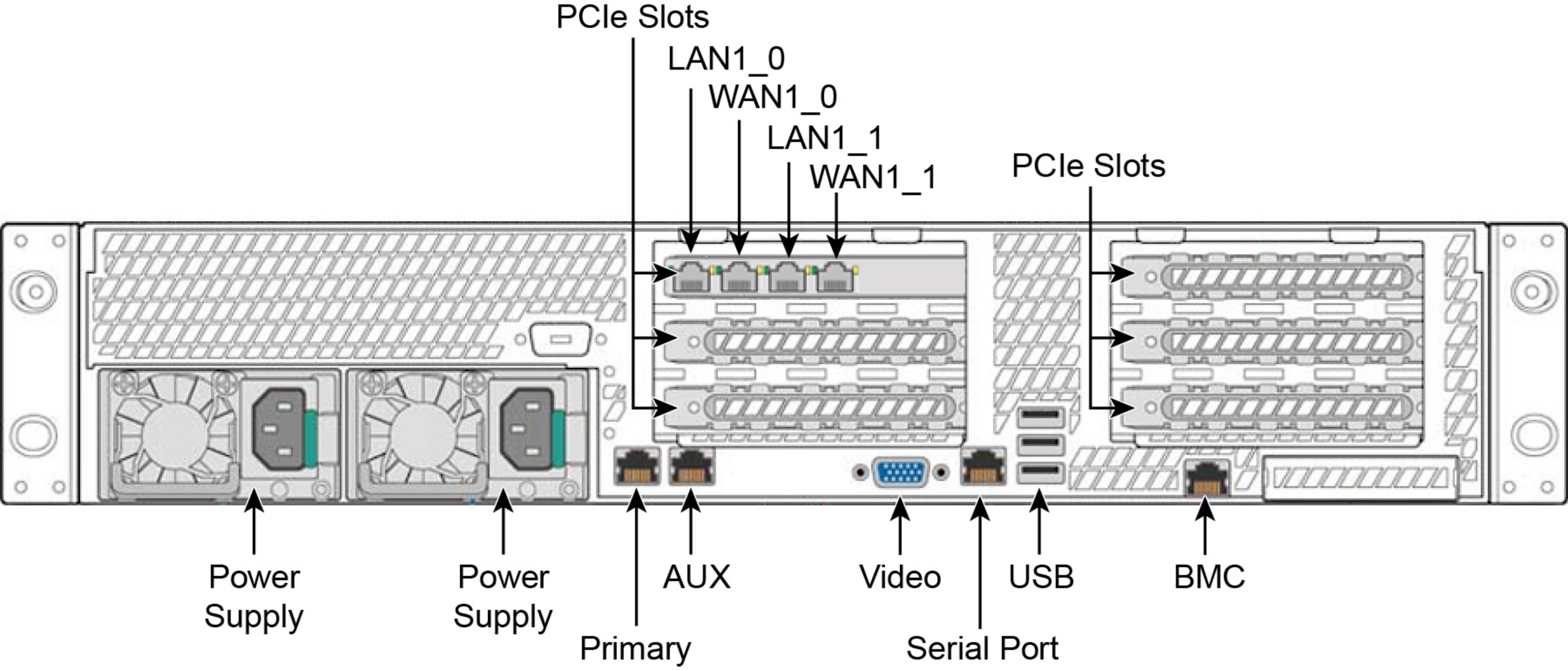
LED/button | Description |
ID LED/Button | On = Blue (System identified remotely on the server.) Off = Off (System not identified.) Press the system ID button when the system AC (Alternating Current) is on. The system ID LED indicates the system is identified with a blue light. Users from a remote site can activate the ID LED by inputting commands in IPMI. For details, contact Riverbed Support at https://support.riverbed.com. |
Primary and AUX Port LEDs | Left LED Link = Green Activity = Blinks green No Link = Off Right LED 10 Mbps = Off 100 Mbps = Green 1000 Mbps = Amber |
Four-Port 1 GbE Copper Bypass Card LEDs (preinstalled) | Link/Activity LED Link = Green Activity = Blinks green Speed/Bypass/Disconnect LED 1000 Mbps = Yellow 100 Mbps = Green 10 Mbps = Off Bypass = Blinks green Disconnect = Blinks yellow |
Power Supply LEDs | Power On and Healthy = Green Standby = Blinks green Power Off = Off Unplugged or power lost but second power supply has power = Amber for about 5 seconds, and then turns Off Power on with warning = Blinks amber to indicate high temperature, high power, high current, or slow fan. |