Installing NICs in 9600 Appliances
This chapter describes how to install network interface cards (NICs) in Interceptor (IC) 9600 appliances. It includes these sections:
Before you begin
During installation, make sure you follow proper ESD procedures when you handle the NIC:
• Wear properly grounded ESD straps.
• If an ESD strap isn’t available, touch a properly grounded metallic surface prior to handling the NIC.
• Don’t touch the electronic components on the NIC.
Before you install a NIC, ensure the card meets the software and appliance requirements described in the following sections.
Supported cards for IC 9600 appliances
This section describes the software requirements and cards that you can install on IC 9600 appliances.
All supported network cards for IC 9600 appliances support fail-to-block mode. For details, see
About Fail-to-Block Mode.IC 9600 supported NICs
The following tables summarize the add-on cards and software requirements for the IC 9600 appliances.
9600 NICs | Size (*) | Manufacturing part no. | Riverbed orderable part no. | Supported Interceptor versions |
Four-Port 1-GbE Copper Base-T | HHHL** | 410-00115-01*** | NIC-1-001G-4TX-BP | 4.5.2 or later |
Two-Port 1-GbE Fiber SX | HHHL | 410-00113-01 | NIC-1-001G-2SX-BP | 4.5.2 or later |
Four-Port 1-GbE Fiber SX | FHHL | 410-00122-01 | NIC-1-001G-4SX-BP | 4.5.2 or later |
Two-Port 1-GbE Fiber LX | HHHL | 410-00114-01 | NIC-1-001G-2LX-BP | 4.5.2 or later |
Four-Port 1-GbE Fiber LX | FHHL | 410-00123-01 | NIC-1-001G-4LX-BP | 4.5.2 or later |
Two-Port 10-GbE Fiber SR* | FHHL | 410-00302-03 | NIC-1-010G-2SR-BP | 4.5.2 or later |
Two-Port 10-GbE Fiber LR* | FHHL | 410-00301-03 | NIC-1-010G-2LR-BP | 4.5.2 or later |
Two-Port 40-GbE Fiber SR* | FH9.5” | 410-00193-01 | NIC-1-040G-2SR4-BP | 7.0 or later |
Two-Port 40-GbE Fiber LR* | FH9.5” | 410-00194-01 | NIC-1-040G-2LR4-BP | 7.0 or later |
Four-Port 10-GbE Fiber SR* | FHFL | 410-00191-01 | NIC-1-010G-4SR-BP | 7.1 or later |
Four-Port 10-GbE Fiber LR* | FHFL | 410-00190-01 | NIC-1-010G-4LR-BP | 7.1 or later |
*These NICs have a power connector cable attached that is not used in the Riverbed SteelHead platforms. The SteelHead systems are designed to fully power these NICs through the interface bus.
**HHHL = Half Height, Half Length; FHHL = Full Height, Half Length; FH9.5” = Full Height, Length 9.5”.
**You might receive a card with the part number 410-00115-11. The -11 denotes a different manufacturing location. The 410-00115-11 card is the same card as the 410-00115-01 card.
The NIC-1-010G-4SR-BP-C and the NIC-1-010G-4LR-BP-C cards are not supported on the Interceptor 9600 due to compliance restrictions.
In-path traffic might slow or fail with the Two-Port 40-GbE SR QSFP+ Fiber (410-00193-01) card and the Four-Port 10-GbE SR Fiber (410-00191-01) card. For a workaround, go to Knowledge Base article
S33925.
For Interceptor 9600 slot restrictions, see
Slot restrictions for IC 9600 appliances.
Slot restrictions for IC 9600 appliances
This table summarizes the maximum number of NICs and slot restrictions for the IC 9600 appliances.
Supported NICs | Quantity | Supported slots |
Interceptor 9600 | | |
1 GbE | 6 | 1-6 |
10 GbE | 4 | 1, 2, 3, 6 |
40 GbE | 2 | 1, 2 |
Installing NICs in IC 9600 appliances
This section describes how to install add-on cards in the IC 9600 appliances.
Figure: Slot locations for IC 9600 appliances identifies the PCIe slot locations for the IC 9600 appliances.
Slot locations for IC 9600 appliances
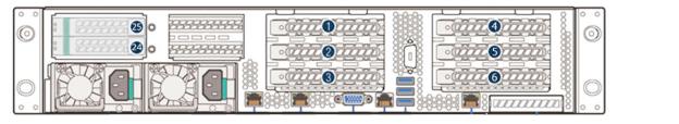
The Interceptor 9600 NIC port numbering is shown in
Figure: GX, IC 9600 bypass card port numbering. The PCI riser cards are located at the same side of the slots. When facing the rear of the chassis, both risers are on the left side of the cards. The physical ports on the NICs are mapped in proximity to the PCI bus edge connector. The port closest to the edge connector is L0, then W0, L1, followed by W1.
GX, IC 9600 bypass card port numbering
Slot restrictions for IC 9600 appliances
Product | Slot guidelines |
Interceptor 9600 | • Appliances ship with a four-port 1-GbE copper bypass card installed in slot 1. You can install a maximum of six 1-GbE NICs in slots 1 to 6 in IC 9600. • The preferred order for populating slots is 2, 3 (if available), 6, 5, and 4. • Install 10-GbE NICs before 1-Gbps NICs when following the preferred slot order. • 10-GbE NICs must be installed in slots 1, 2, 3, or 6; don’t install them in 4, 5. Install 10-GbE NICs before 1-Gbps NICs when following the preferred slot order. You can install a maximum of four 10-GbE NICs in IC 9600. • IC 9600 supports four 10-GbE NICs. The 1-GbE card in slot 1 must be relocated to slot 4 or 5. • 40-GbE NICs must be installed in slots 1 or 2; don’t install in 3, 4, 5, or 6. You can install a maximum of two 40-GbE NICs in IC 9600. • In-path traffic might slow or fail with the Two-Port 40-GbE SR QSFP+ Fiber (410-00193-01) card and the Four-Port 10-GbE SR Fiber (410-00191-01) card. For a workaround, go to Knowledge Base article
S33925. |
To install or replace an add-on card
1. Power down the appliance.
2. Remove the power supply cord.
3. Remove the cables connected to the appliance.
4. Remove the appliance from the mounting rack, if necessary.
5. Remove the chassis cover.
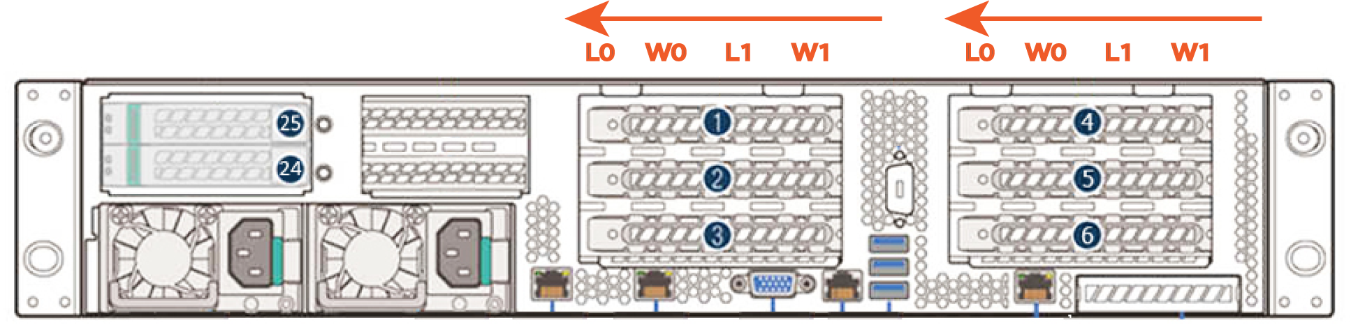
6. Unplug the cables on the SSD boot drive.
Unplugging the SSD drive cable
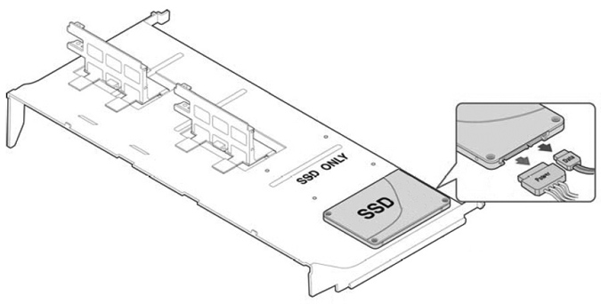
Removing the air duct
The riser assemblies are accessible.
NIC riser assembly
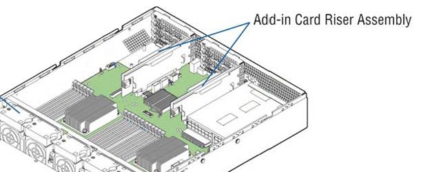
Removing and installing the riser assembly
The network card riser assembly connects the cards to the appliance. You need to remove the assembly to add or replace a card.
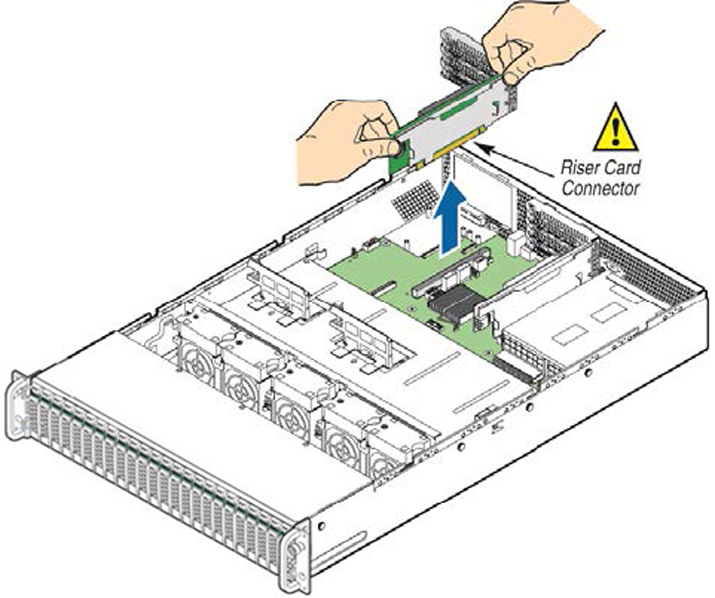
To remove the riser assembly
• Grasp the riser assembly with both hands and pull up to remove from the appliance.
Removing the add-on card riser assembly
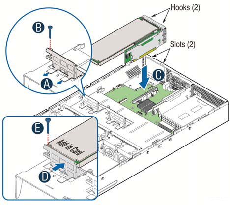
To install the riser assembly with full-length cards
3. Position the riser card edge connector over the server board riser socket and align the two hooks on the back edge of the riser assembly with the slots on the back of the chassis, and then press straight down into riser socket. (See
Figure: Installing the riser assembly, letter C.)
Installing the riser assembly
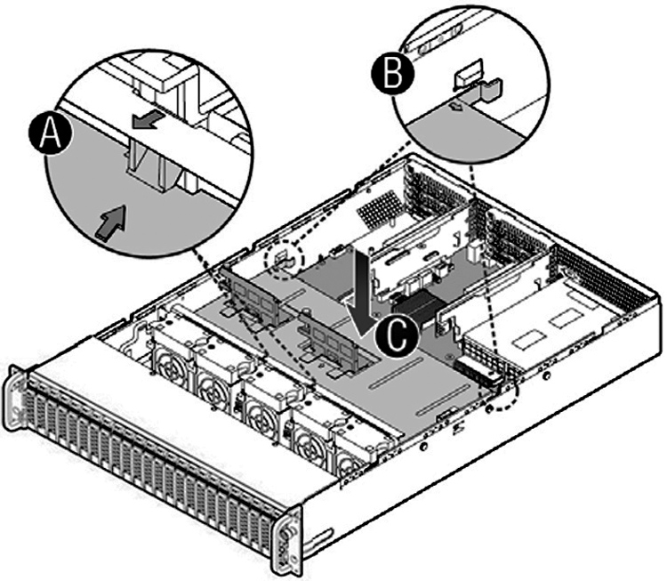
6. To reinstall the air duct, lower the back edge of the air duct to engage the two tabs on the fan bulkhead. (See
Figure: Installing the air duct, letter B.)
Installing the air duct
9. Plug in the SSD boot drive cable.
To install the riser assembly without full-length cards
1. Position the riser card edge connector over the server board riser socket.
2. Align the two hooks on the back edge of the riser assembly with the slots on the back of the chassis.
Installing and replacing an add-on card in 2U appliances
Follow these instructions to install or replace an add-on card in your 2U appliance.
To install or replace an add-on card
1. Remove the riser assembly.
Installing a NIC in the riser connector
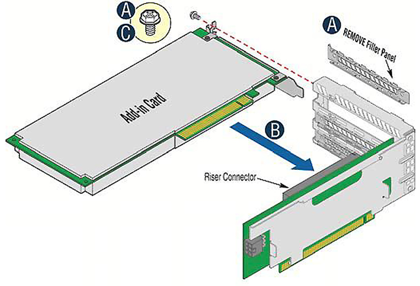
5. Ensure that all empty card slots have filler panels.
7. Replace the cover on the chassis.
8. Connect the cables.
9. Connect the power cords.
10. Power up the appliance and check the status lights.
To remove an add-on card
1. Remove the riser assembly.
Removing a NIC from the riser connector
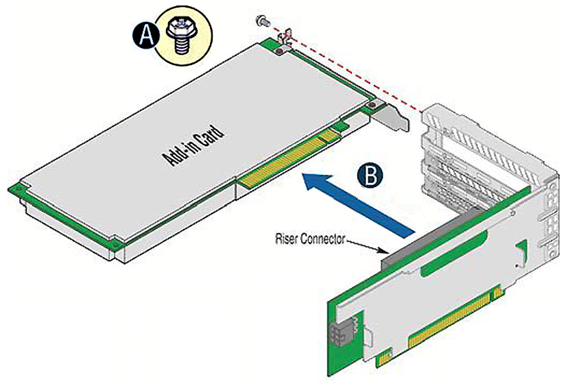
4. Ensure that all empty card slots have filler panels.
6. Replace the cover on the chassis.
To test SteelHead NICs
1. Connect to the SteelHead CLI. For detailed information, see the Riverbed Command-Line Interface Reference Manual.
2. Enter enable mode. At the system prompt, enter the enable command.
3. Verify that the NIC is correctly installed. At the system prompt, enter the show hardware all command.
To reset the main interface and recognize all ports, enter the in-path reset-iface command in the CLI configuration mode.