Installing SteelHead-v on Microsoft Hyper‑V
SteelHead-v is supported on the Microsoft Hyper-V hypervisor. See
Third-party software dependencies for details. For detailed information about Hyper‑V, go to
http://www.microsoft.com/en-us/server-cloud/Hyper‑V-server/Starting with RiOS 9.7, physical in-path, virtual in-path, and out-of-path modes are supported. Physical in-path modes require the use of a bypass card. For information about configuring bypass cards for a SteelHead-v running on Hyper‑V, see the “Configuring a NIC bypass card for Hyper‑V” section in the Network and Storage Card Installation Guide. In versions 8.0.3 to 9.6, virtual in-path and out-of-path modes are supported, while direct in-path deployment with a Riverbed NIC is not.
The underlying RiOS image is the same as the physical models. After you install the SteelHead-v package, you can upgrade the virtual appliance using a standard image.
This chapter describes how to install and configure SteelHead-v on Hyper‑V. It includes these sections:
Basic steps for installing SteelHead-v on Hyper-V
This section provides an overview of the basic steps to install and configure SteelHead-v on Hyper‑V. Detailed procedures are provided in the sections that follow.
Task | Reference |
1. Confirm that Hyper‑V is provisioned to run the SteelHead-v model. Check to make sure the resources are available before choosing your model. | |
2. Obtain the SteelHead-v package from Riverbed Support. | |
3. Gather network settings for the configuration wizard. | |
4. Install and configure the SteelHead-v image. | |
5. Power on the VM, start the SteelHead-v, and log in. | |
Obtaining the SteelHead-v for Hyper-V software package
The Hyper‑V SteelHead-v package is a zip file containing the management Virtual Hard Disk (VHD) and an install script. To download the zip package from the Riverbed Support site, go to
https://support.riverbed.com. Access to software downloads requires registration.
During installation, you will unzip the package and run the RIVERBED_INSTALL.ps1 script from Windows PowerShell. To run the script, you might need to configure the security policy to “Unrestricted.”
To configure the security policy
1. Right-click the Windows PowerShell program and select Run as administrator.
2. At the command prompt, enter the Set-ExecutionPolicy Unrestricted command.
Completing the preinstallation checklist
This section lists the parameters you specify to complete the initial configuration of SteelHead-v. Be prepared to provide values for the network settings listed in this checklist when prompted by the installation script.
Network setting | Your value |
InstallLocation (required) | Path to the directory for the VM. |
Model (required) | The hardware model to be configured. Choosing the model causes the installation to allocate the correct disk sizes, memory, and CPU cores. |
VHDLocation (optional) | The default is the selected directory. The script looks for the management VHD image at this location. |
VMName (optional) | The default is Riverbed SteelHead. |
ComputerName (optional) | The default is localhost. If you are installing to a remote computer, enter the name of that computer. |
NumInpaths (optional) | The default is 1. Enter the number of in-path pairs to create. |
SegstoreSize (optional) | The default is the allocated disk size for your model. Enter a value in bytes (B) or gigabytes (GB) to override the allocated size. |
PowerOn (optional) | Include this setting if you want the SteelHead-v to start up after the install is complete. |
PrimaryNetwork (optional) | Enter the name of the vSwitch to connect the primary NIC to. |
AuxNetwork (optional) | Enter the name of the vSwitch to connect the auxiliary NIC to. |
{WL}an{01234}_0Network (optional) | Enter the name of the vSwitch to connect the named network interface to. |
Configuring virtual switch interfaces for VLAN-tagged and non-VLAN-tagged networks
Before you install the SteelHead-v, determine if your network uses VLAN tagging. Specific configuration is required depending on the VLAN configuration. This table shows the configuration to use for networks with and without VLAN tagging. Specific procedures, including screen shots, are included in the
To configure the virtual switch interfaces and
To configure the Hyper‑V server’s interface sections.
Type of adapter or interface | VLAN-tagged packet setting | Non-VLAN-tagged packet setting |
Windows network adapter configuration for VLAN | VLAN enabled | VLAN disabled |
Hyper‑V virtual switch network interface configuration | VLAN disabled | VLAN disabled |
Hyper‑V VM network interface configuration | VLAN enabled | VLAN disabled |
RiOS in-path interface configuration | VLAN ID 0 | VLAN ID 0 |
Installing SteelHead-v on a Hyper-V virtual machine
This section describes how to install SteelHead-v on Hyper‑V.
Note: If the install script displays a message about insufficient disk space, try using the parameter SegstoreSize <size> GB and set the size to an appropriate value. The management disk uses 38 GB in addition to this allocation for xx55 VCX models and occupies a minimum of 20 GB additional space for performance-tier based models.
To begin the SteelHead-v installation
2. Extract the zip file into the directory you want to use.
3. Open Windows PowerShell.
4. Run the install script.
You can enter all the script parameters as part of the run command. If you do not enter any parameters, you are prompted for the two required parameters.
5. Enter the install location.
6. Enter the SteelHead hardware model.
The message “Creating new VM” appears. VM creation can take 30 minutes or more to complete.
7. After the VM creation is complete, check all the VM settings in the Hyper‑V Manager to verify they are correct.
To configure the virtual switch interfaces
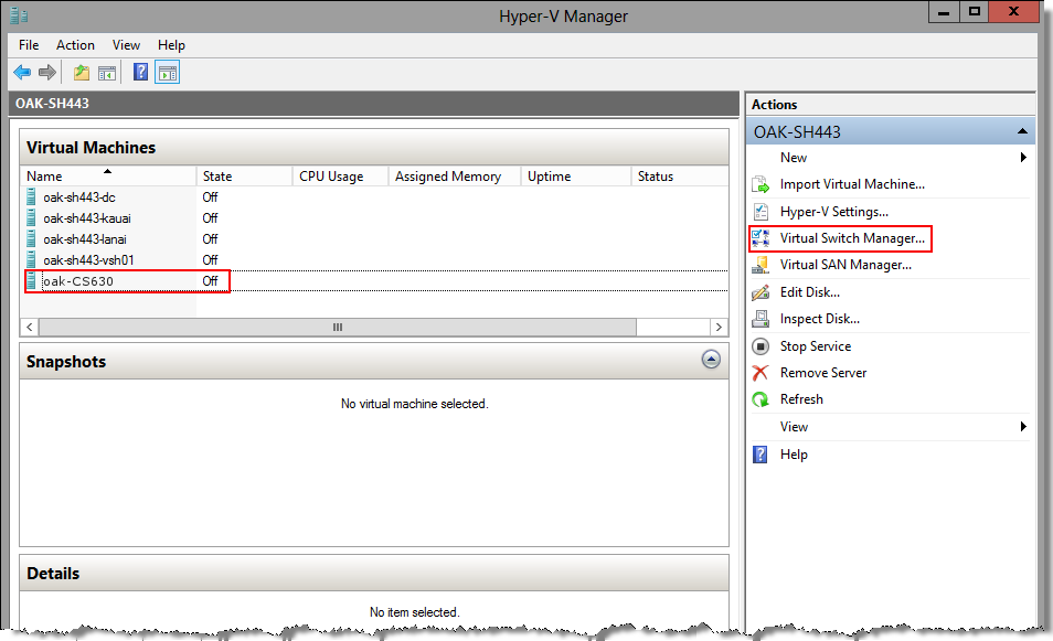
1. On your Windows desktop, open the Hyper‑V Manager.
2. Open the Virtual Switch Manager by selecting the virtual machine in the left-hand Virtual Machines panel; then select Virtual Switch Manager in the right-hand Actions panel.
Figure: Opening the Virtual Switch Manager page
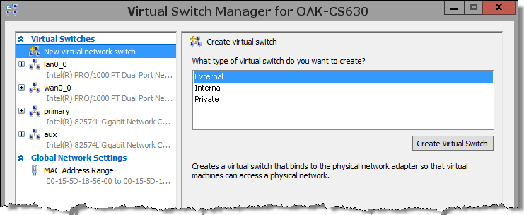
3. Create a virtual switch for each SteelHead-v interface (for example, primary, aux, lan0_0, and wan0_0).
Figure: Virtual Switch Manager page
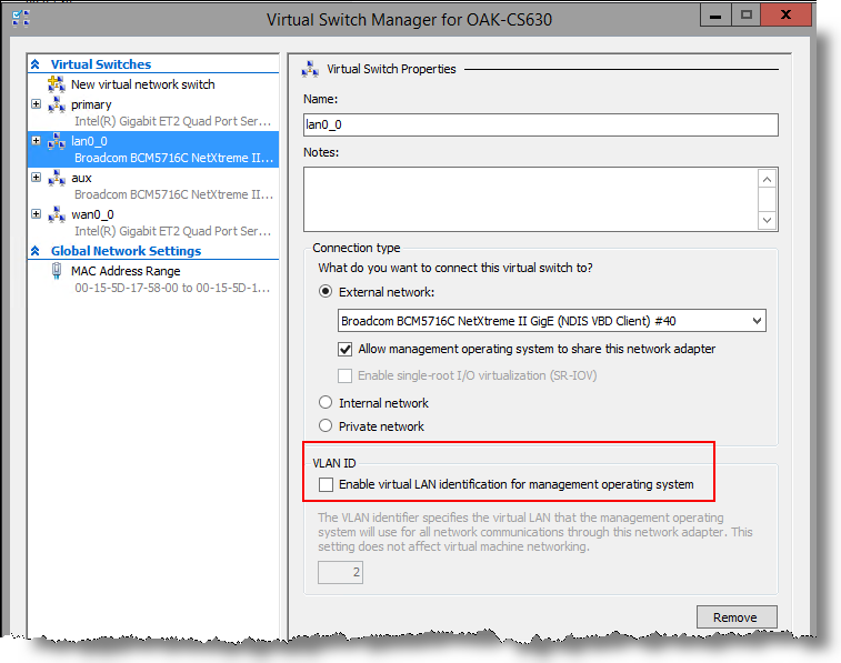
Note: Be sure that the Enable virtual LAN identification for management operating system check box is not selected. You do not enable VLAN tagging at the Hyper‑V Virtual Network Switch level.
Figure: Checking virtual LAN identification for the management operating system
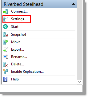
4. Select Settings in the right-hand Riverbed SteelHead pane to open the Settings window.
Figure: VM options
5. Connect each virtual switch interface to the corresponding virtual switch.
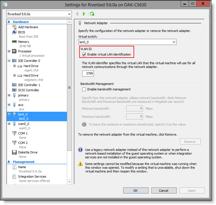
• If your network uses VLAN tagging, select the Enable virtual LAN identification check box for the LAN0_0 and WAN0_0 interfaces.
• If your network does not use VLAN tagging, clear this check box.
Figure: Enabling virtual LAN identification
To power on and complete configuration of the SteelHead-v
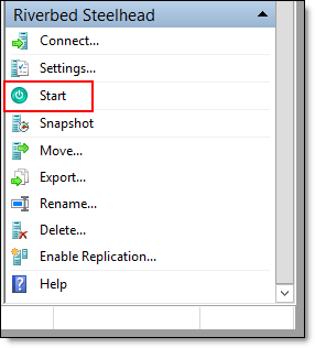
1. Select Start in the right-hand Riverbed SteelHead pane to power on the VM.
Figure: VM options
2. Select Connect to connect to the terminal window.
4. Log in to SteelHead-v as an administrator.
The default administrator login is admin and the default password is password.
Note: After you deploy SteelHead-v, set the reserve weight for CPU to 100 and the memory weight to High.
To configure the Hyper‑V server’s interface
1. On the Windows server, choose Control Panel > Network and Internet > Network Connections.
2. Right-click the network connection for the Hyper‑V server’s interface and select Status.
3. Click Properties.
4. Make sure that the Networking tab is selected, and then click Configure.
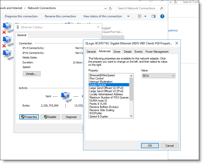
5. Select the Advanced tab.
6. Set the jumbo frame size to 9014 bytes by selecting Jumbo Packet in the Property area and selecting 9014 in the Value drop-down list.
Figure: Setting the jumbo packet to 9014 bytes
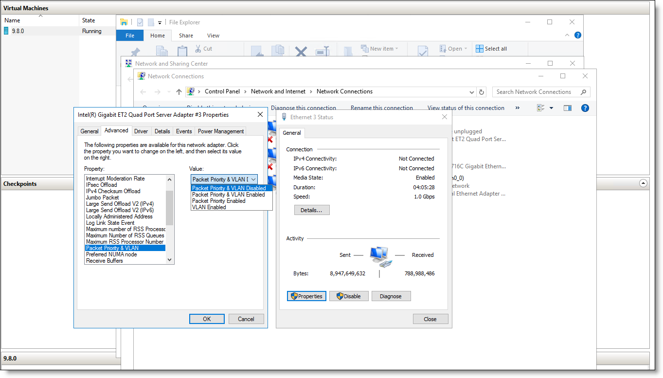
7. Set the VLAN value by selecting Packet Priority & VLAN in the Property area, and set the value for your network.
– For a VLAN-tagged network, select Packet Priority & VLAN Enabled.
– For a non-VLAN-tagged network, select Packet Priority & VLAN Disabled.
Figure: Setting the VLAN value
8. Click OK.
9. Click Close to close the interface Status window.
10. Enable MAC address spoofing on the virtual network adapters by running PowerShell as an administrator on the Windows server and entering this command:
set-vmnetworkadapter -VMname “<vm-name>” -computername <hyper‑v-host>
-name <v-network-adapter> -macaddressspoofing on
Where <vm-name> is the name of the virtual machine, <hyper‑v-host> is the name of the Hyper‑V host, and <v-network-adapter> is the name of the virtual network adapter.
This example enables MAC address spoofing for the lan0_0 and wan0_0 interfaces on the virtual machine 9.7.0 and Hyper‑V host oak-cs784.
Administrator> set-vmnetworkadapter -VMname “9.7.0” -computername oak-cs784 -name lan0_0
-macaddressspoofing on
Administrator> set-vmnetworkadapter -VMname “9.7.0” -computername oak-cs784 -name wan0_0
-macaddressspoofing on
11. Verify that MAC address spoofing has been enabled by entering this command:
Get-VMNetworkAdapter -VMname <vm-name> -computername <hyper‑v-host> |fl Name,macaddressspoofing
Where <vm-name> is the name of the virtual machine and <hyper‑v-host> is the name of the Hyper‑V host.
This example displays MAC address spoofing status for the configuration in a formatted list (fl) format.
Get-VMNetworkAdapter -VMname “9.7.0” -computername oak-cs784 |fl Name,macaddressspoofing
Name : primary
MacAddressSpoofing : Off
Name : aux
MacAddressSpoofing : Off
Name : lan0_0
MacAddressSpoofing : On
Name : wan0_0
MacAddressSpoofing : On
Troubleshooting Hyper-V installations
• VM missing interface messages - After powering on the VM, if you see messages about missing interfaces or disks, check these troubleshooting tips:
– If there are missing interfaces on the SteelHead-v, check the VM settings and verify that you are using synthetic NICs (not legacy), and that the cards are connected.
– If RiOS logs messages about missing disks, ensure that the RiOS data store disk is present and is in slot 1 of controller 0.
• Hyper-V configuration not saved - After every change to Hyper-V configuration settings, you must shut down and restart the Hyper-V.
• Incorrect NIC-to-interface mapping - Be sure that the lan0_0 and wan0_0 interfaces are mapped to the correct NIC on the Windows server. If your server uses a NIC bypass card, see the “Configuring a NIC bypass card for Hyper-V” section of the Network and Storage Card Installation Guide for details.
For more troubleshooting information, see
Troubleshooting SteelHead-v. Manually installing SteelHead-v on Hyper‑V
This section describes how to manually install SteelHead-v from the Hyper‑V Manager.
To manually deploy SteelHead-v from the Hyper‑V Manager
1. Create a new VM.
You need the correct amount of memory and CPU for the hardware model.
2. Remove the CD drive.
3. Create a fixed-size disk for the management VHD of the correct size for the model.
You can perform this step from the Hyper‑V Manager, or you can use the Convert-VHD script.
4. Add the management VHD as the disk in controller 0 slot 0.
5. Create a fixed-size disk of the correct size for the SteelHead-v model to serve as the RiOS data store.
6. Add this disk to controller 0 slot 1.
7. Create a virtual NIC for primary and auxiliary, and create two for each in-path pair you want.