Replacing 2U Appliance Components
This chapter describes how to replace hard disk drives (HDDs), solid-state drives (SSDs), memory modules, fans, and power supply units in 2U appliances. Use caution when you remove or replace components; they can become hot to the touch.
About required tools
You need the following tools and equipment to replace appliance components:
• You must use approved components for the appliance to function properly. Installation of unapproved components will result in boot failure. To order components, contact Support at https://support.riverbed.com.
When you replace appliance components, you must wear a grounded ESD antistatic strap to protect the hardware against electrostatic discharge. Make sure that the strap makes skin contact prior to handling equipment.
Removing the chassis cover on 2U appliances
These sections describes how to remove the chassis cover on 2U xx90, xx80, and 9800 appliances.
Removing the chassis cover on 2U xx90 appliances
1. Power down the appliance and unplug all peripheral devices and the power cable.
Removing the chassis cover screws on the 2U xx90 appliance
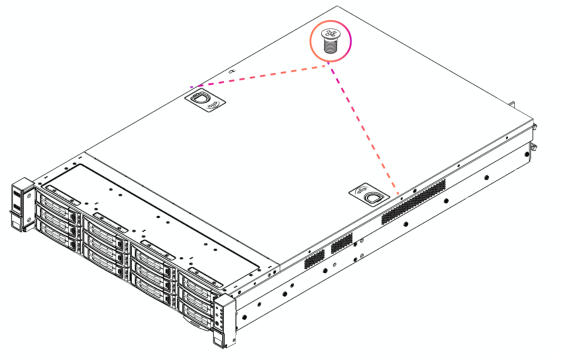
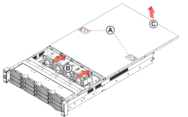
Removing the chassis cover on 2U xx90 appliances
Removing the chassis cover on 2U xx80 appliances
1. Power down the appliance and unplug all peripheral devices and the power cable.
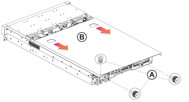
Removing the chassis cover on the 2U xx80 and 9800 appliance
Removing riser brackets and air duct covers in 2U appliances
These sections describes how to remove the riser bracket in 2U xx90 xx80, and 9800 appliances and how to remove the air duct cover in 2U xx80 and 9800 appliances.
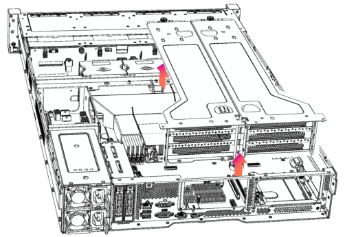
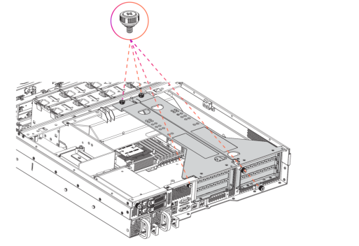
Removing the riser bracket in 2U xx90 appliances
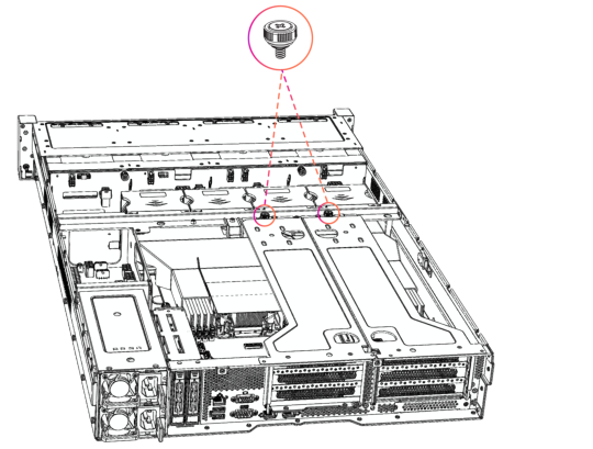
Loosening the riser brackets retaining screws in the 2U xx90 appliance
3. Lift straight up to remove the riser brackets from the chassis.
Lifting the riser bracket out of the 2U xx90 chassis
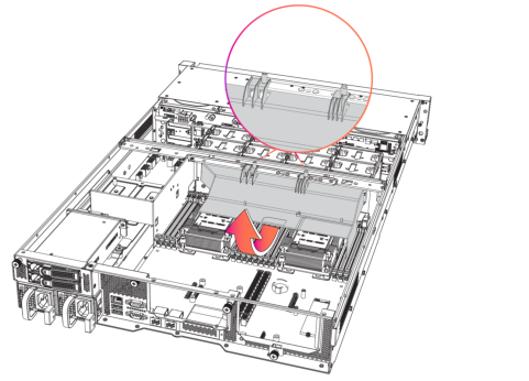
Removing the riser bracket and air duct cover in 2U xx80 appliances
Loosening the riser bracket retaining screws in the 2U xx80 appliance
Removing the air duct cover in the 2U xx80 and 9800 appliance
Replacing front drive trays in 2U appliances
This section describes how to remove the front drive trays in 2U xx90, xx80, and 9800 appliances and rear drive trays in 2U xx80 and 9800 appliances.
Replacing the front drive trays in 2U xx90 and xx80/9800 appliances
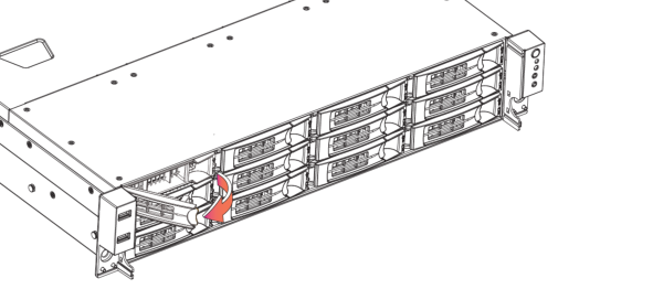
1. Remove the bezel.
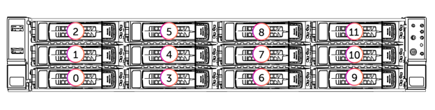
2. Identify the faulty disk drive. The disk drive LED is red for failed drives.
Disk drive numbers on 2U appliances
3. Press the locking-lever latch and pull the locking lever open.
Removing a disk drive from the 2U appliance
4. Slide the faulty disk drive tray out.
5. Slide in the new disk drive until it engages with the back connectors in the chassis.
6. Push to secure the locking lever until it clicks into place. The disk drive LED lights green when connected.
The new disk drive runs a self-test automatically and then starts working with the other drives without any setup or configuration needed. For SteelHead appliances, rebuilding the new drive takes about 3 to 4 hours, depending on system load. You can set up the web interface to send an email notification to the administrator once the rebuild is complete.
Replacing rear drive trays in 2U xx80 appliances
Some 2U xx80 and 9800 appliances include two hot-swappable 2.5-inch SSDs on the rear of the appliance.
1. Identify the faulty disk drive.
2. Press the locking-lever latch and pull the locking lever open.
Removing the 2.5 inch SSD on the rear of the 2U xx80 appliance
3. Insert the drive into the chassis.
4. Press the locking lever to secure the drive.
Replacing power supply units in 2U appliances
These sections describes how to replace power supply units in 2U xx90, xx80, and 9800 appliances.
Replacing power supply units in 2U xx90 appliances
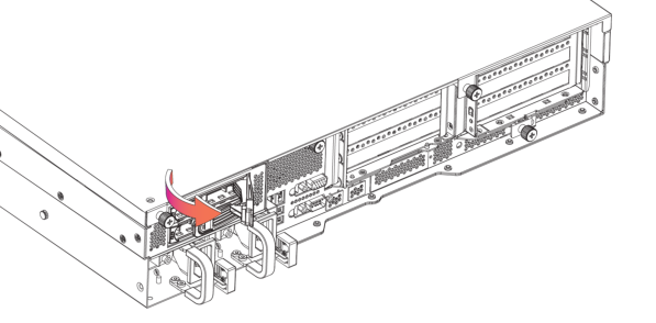
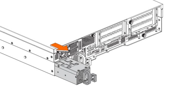
1. Locate the defective power supply (PS) unit and remove the power cord.
Pressing the power supply unit latch and removing the power supply from the 2U xx90 appliance
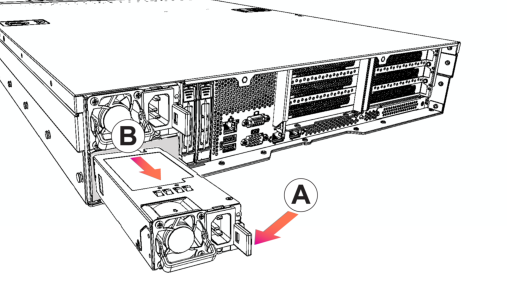
3. Slide the power supply unit out of the chassis. Put the defective power supply unit aside; wait until it cools down before touching it.
4. Press and hold the latch and push the power supply into the chassis using the handle.
5. Plug the AC power cord into the new power supply unit.
Replacing power supply units in 2U xx80 appliances
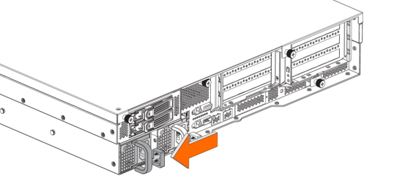
1. Locate the defective power supply (PS) unit and remove the power cord. When facing the rear of the appliance, PS0 is on the right and PS1 is on the left.
2. Press the latch and pull the power supply unit toward you.
Pressing the power supply unit latch on the 2U xx80 and 9800 appliance
3. Slide the power supply unit out of the chassis. Put the defective power supply unit aside; wait until it cools down before touching it.
Removing the power supply from the 2U xx80 and 9800 appliance
4. Press and hold the latch and push the power supply into the chassis using the handle.
5. Plug the AC power cord into the new power supply unit.
Replacing memory modules in 2U appliances
This section describes how to replace memory modules and slot locations in 2U xx90, xx80 and 9800 appliances.
1. Power down the appliance.
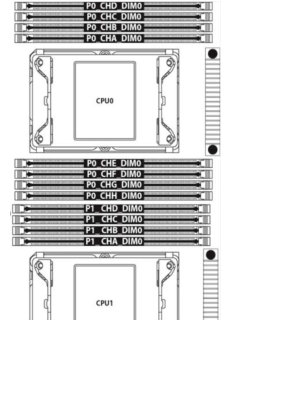
Memory module slot locations in the 2U xx90 appliance
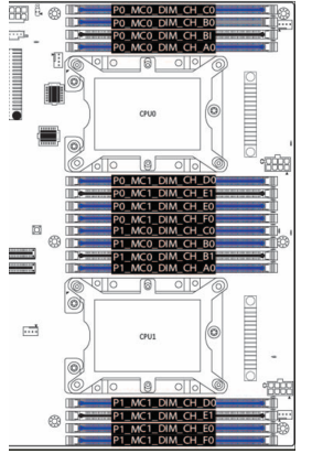
Memory module slot locations in the 2U xx80 and 9800 appliances
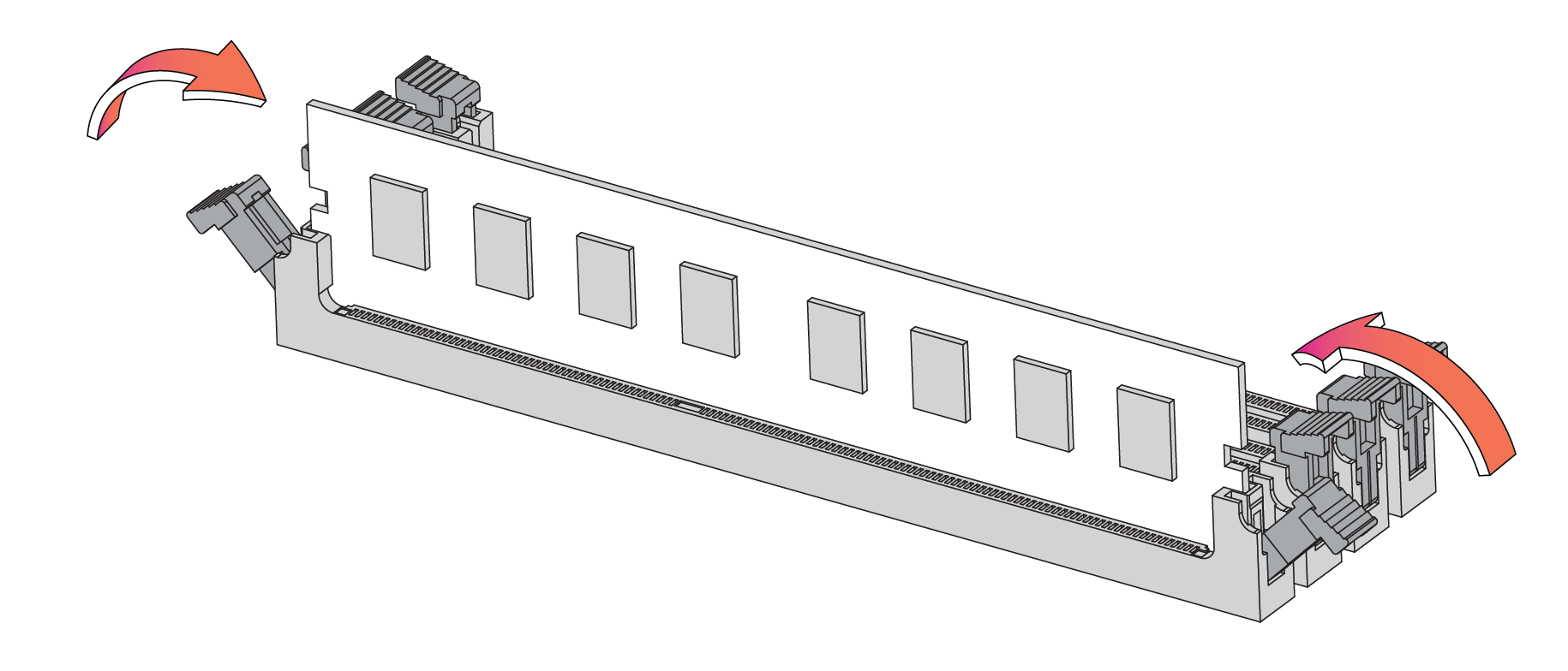
5. Press the clips outward to unlock them and gently pull the memory module out of the slot.
Releasing the locking clips
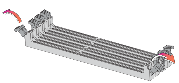
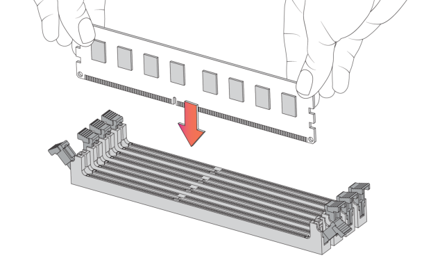
6. Align the memory-module edge connector and insert it into the slot. When inserted properly, the memory slot locking levers lock automatically onto the indentations at the ends of the module.
Inserting the memory modules
7. Press the clips inward to lock the module in place.
Ensuring the locking levers are locked.
8. Ensure that all clips are in the upright locked position.
10. Replace the chassis cover.
11. Replace the power cords and peripherals.
12. Power on the appliance.
Replacing fans in 2U appliances
These sections describe how to remove the fans in 2U xx90, xx80, and 9800 appliances.
Replacing fans in 2U xx90 appliances
1. Power down the appliance. The fans are not hot-swappable.
2. Remove the chassis cover.
3. Identify the faulty fan.
4. If necessary, disconnect the fan power cable from the backplane.
Removing a fan in the 2U xx90 appliance
6. Insert the new fan into the fan slot. Ensure that the tab
7. Plug in the fan power supply into the backplane.
8. Replace the chassis cover.
Replacing fans in 2U xx80 and 9800 appliances
1. Power down the appliance. The fans are not hot-swappable.
2. Remove the chassis cover.
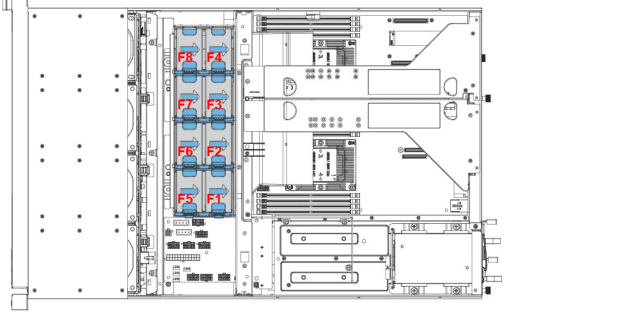
Fan layout in the 2U xx80 and 9800 appliance
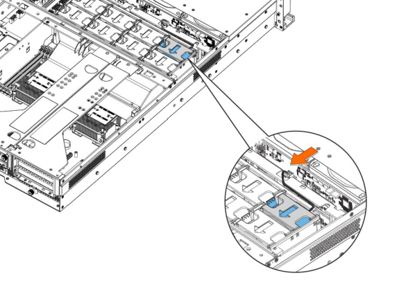
4. Disconnect the fan power cable from the backplane.
Disconnecting the fan power cable in the 2U xx80 and 9800 appliance
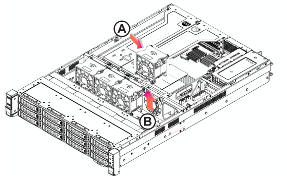
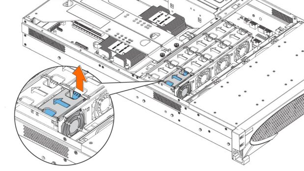
5. Press the blue button and pull the fan straight up to remove it.
Removing the faulty fan in the 2U xx80 and 9800 appliance
6. Insert the new fan into the fan slot.
7. Plug in the fan power supply into the backplane.
8. Replace the chassis cover.