SteelConnect Ports
This topic describes ports and port settings in SteelConnect. It includes these sections:
Port overview
A SteelConnect port on an appliance is an Ethernet interface used either for WAN or LAN.
The number of physical interfaces supported for each branch gateway model are:
•SDI-130: 2
•SDI-330: 2
•SDI-1030: 12
The 130 and 330 gateway models have two physical interfaces that can be used as uplink interfaces. There are also eight switch ports on the 130 and 330 that cannot be used as uplink interfaces, but only as zone or multizone interfaces.
On the 1030 gateway model, four of the 12 ports are Small Form-factor Pluggable (SFP+) ports.
After attaching a modem to one of the interfaces on a 130 or 330 gateway, you can only support two WANs on that device. For example, you can support MPLS on interface 1 and support internet through an LTE modem on interface 2.
Virtual gateway interfaces
Virtual gateways require a minimum of two interfaces: one LAN and one WAN. The default configuration ships with three interfaces, but you can add more by modifying the VM configuration outside of SCM. Adding more WAN interfaces increases your uplink options.
The number of virtual gateway interfaces supported depends on how many the hypervisor allows. For example, ESXi 5.5 supports ten interfaces for the virtual gateway model SDI-VGW.
The virtual gateway interfaces are labeled as LAN on the Ports page.
Port settings and status
You can use the Ports page to:
•set the port mode: singlezone, multizone, uplink, or mirrored uplink. Selecting singlezone is equivalent to putting a port in access mode. The zone is assigned to only one VLAN. Selecting multizone enables the port to function as an 802.1q trunk.
Enable 802.1x authentication for network access control.
•set autotrunking on or off. Enable autotrunking to interconnect and form a trunk when more than one zone is mapped across it. For example, as soon as you connect a SteelConnect access point to a SteelConnect switch, they negotiate a trunk automatically. The access point will have a trunk port configured with all zones for that site.
By default, autotrunking is enabled. When autotrunking is enabled, 802.1x authentication is disabled and vice versa.
•view the MAC addresses for which traffic is being forwarded through the port.
•view the raw port counters for advanced debugging.
•label the patch panel socket or wall socket to which the port is connected.
To view ports
•Choose Appliances > Ports.
Ports page
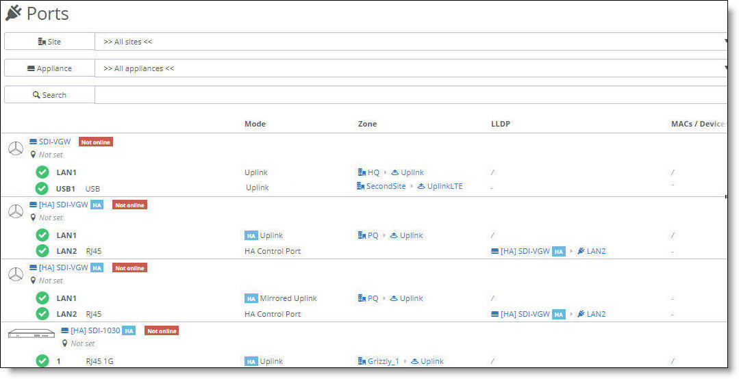
SteelConnect Manager displays the ports and port status, their operation mode, zones, and more.
The icons in front of the port indicate status:
Icon | Status |
|
The link is up.
|
|
The link is down.
|
|
The port is in a blocking state because either the Spanning Tree Protocol (STP) is discarding packets or there is an 802.1x authentication failure.
|
To view more port details
1. Select a port.
2. Select the Info/Mode tab.
To set the port mode
1. Select a port.
2. Select the Info/Mode tab.
3. Next to Port mode, select a mode from the drop-down menu.
•When enabling single zone, select the zone. The zone is assigned to only one VLAN.
•When enabling an individual uplink, select the uplink.
By default, a port is automatically configured for multizone when it’s connected to another SteelConnect appliance. Multizone allows the port to function as an 802.1q trunk. For example, as soon as you connect a SteelConnect access point to a SteelConnect switch, they negotiate a trunk. The access point will have a trunk port configured with all zones for that site.
On a USB port, select uplink (the only available mode).
For details on selecting the Uplink and Mirrored Uplink port mode options for branch HA partners, see
Port configuration.
4. Click Submit.
Checking the connection status for a USB port
On the Info/Mode tab for a USB port, the connection status displays whether the LTE modem is connected to the gateway. When the connection status reports that the modem is connected to the appliance, but the link status is down, it means that something went wrong when the modem tried to connect to the cellular network. For details, you can view the event log for the modem states during the connection process.
Hot plugging an LTE modem in an SDI-130 gateway over an AWG 28 USB cable can cause a significant voltage drop (~2V). The voltage drop might cause the SDI-130 to reboot. We recommend that you don’t hot plug a USB modem, but if it is necessary, use an AWG 26 or thicker cable with a lower resistance.
To view events
•Select the Events tab or choose Visibility > Event Log.
LTE modem event log states
Modem event | Meaning |
PIN invalid | The PIN that the user set up is invalid. |
PIN locked | An invalid PIN has been entered for the second time and the appliance has locked the PIN for the subscriber identity module (SIM). |
Registered | The modem was registered on the network. |
No network | The modem was not registered on the network. |
Connected | The connection to the wireless distribution service was successful. |
Start network failed | The connection to the wireless distribution service failed. |
Configured | The Layer 3 configuration was successful. |
IP setup failed | The Layer 3 configuration was unsuccessful. |
To disable autotrunking
1. Select a port.
2. Select the Advanced tab.
3. Next to AutoTrunking, click Off.
4. Click Submit.
To override a port’s default MAC address
1. Select a port.
2. Select the Advanced tab.
3. Next to Virtual MAC, specify a MAC address.
4. Click Submit.
To provide a socket label to the port
1. Select a port.
2. Select the Info/Mode tab.
3. After Patch Label, type a label up to 16 characters long.
4. Click Submit.
Enabling port-based network access control
To better protect a network from unauthorized systems and users, you can enforce access control on the gateways by enabling port-based authentication. Port-based network access control, or Layer 2 access control, protects the network from rogue and potentially malicious users by preventing access to network resources until a client is authorized using 802.1x.
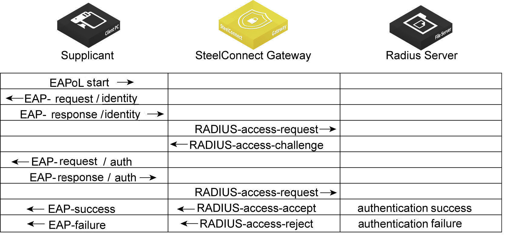
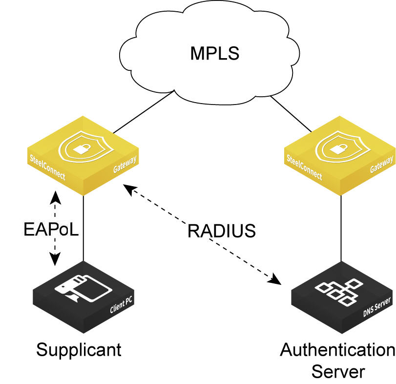
Gateway models 130 and 330 can use 802.1x authentication between a client, known as a supplicant, and a RADIUS server using an Extensible Authentication Protocol (EAP) method. The RADIUS server is responsible for authenticating users. The gateway acts as an authenticator between the supplicant and the RADIUS server. The supplicant is a device that wants to connect to the network. Until the supplicant’s identity has been validated and authorized by the RADIUS server, the gateway prevents access to the network.
What is the gateway’s role in the authentication process?
The gateway performs EAP over LAN (EAPoL) exchanges with the supplicant and converts these exchanges to RADIUS access-request messages. The access-request messages are sent to the RADIUS server's IP address without changing anything. The RADIUS server verifies the supplicant’s credentials and transmits a response back to the gateway acting as the authenticator. After the gateway receives a RADIUS access-accept message from the RADIUS server, it allows the supplicant access to the network.
802.1x authentication process
Topologies
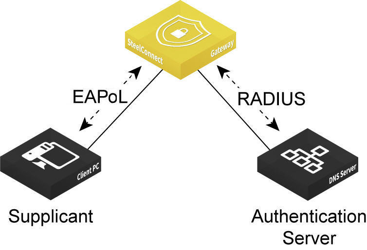
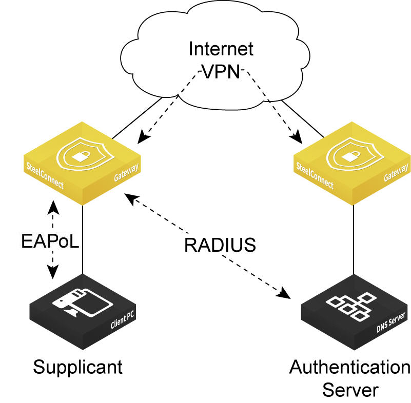
The gateway must be able to reach the RADIUS authentication server using one of these methods:
•Through the LAN using the same or different VLAN zone.
•Over the VPN.
•Over the MPLS.
Port-based authentication through the LAN
Port-based authentication through the VPN
Port-based authentication through the MPLS
To enable 802.1x authentication
2. Choose Appliances > Ports.
3. Select the appliance.
4. Select the port on which to enable 802.1x. The port must use singlezone mode. Multizone mode is not supported.
5. Select the Advanced tab.
6. Next to 802.1X, click On. By default, 802.1x authentication is disabled.
Enabling 802.1x authentication on a port
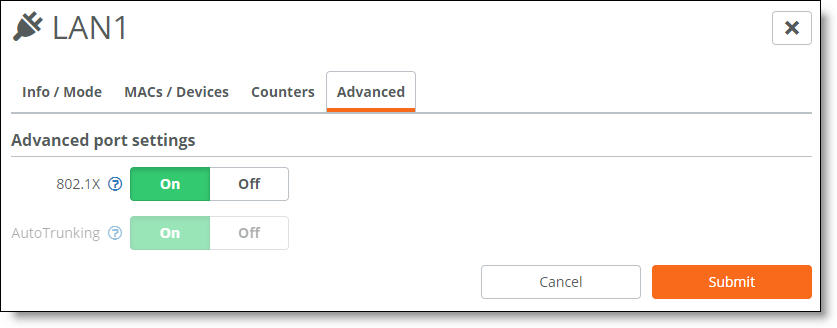
The system dims the autotrunking feature because autotrunking and 802.1x authentication are mutually exclusive.
7. Click Submit.
Give a client a couple of seconds to connect to the gateway. If necessary, enter the security credentials on the client to allow it to use network authentication at the port.
To verify 802.1x authentication
•Select the Info/Mode tab.
When the port is using 802.1x authentication, “Authenticated” appears next to 802.1X.
The Info/Mode tab reports any changes in the link state. For example, if the cable to the client is unplugged, “Unauthenticated” appears next to 802.1X.
