Designing a Network
Creating sites
A site is a physical location of one or more office buildings, a hosting center, or a cloud location that make up the organization. A site houses a SteelConnect gateway and uses a permanent DNS alias. You can create a site without an appliance and add the appliance later. When you create a site, you’re essentially configuring the location of each network you want to participate in the full-mesh VPN.
To speed up site definition for multiple sites, you can define sites in the comma-separated values (CSV) file format and import all of the definitions into SCM at once. The site definitions include the name and location of the site, the time zone, site tags, and so on.
To create a new site
1. Choose Network Design > Sites.
2. Click Add Site(s).
3. Select New Site to add a single site.
4. Type a site tag, which is a name for the site: for example, NY. Don’t use spaces in the tag.
Don’t mistake the site tag with the tags mentioned in
To add tags to a site. This site tag is simply a display label that gives a name to the site. The tags you add on the Location tab are more powerful because they let you group and add structure to sites.
5. Type a site description: for example, Modesto.
6. Type the site address.
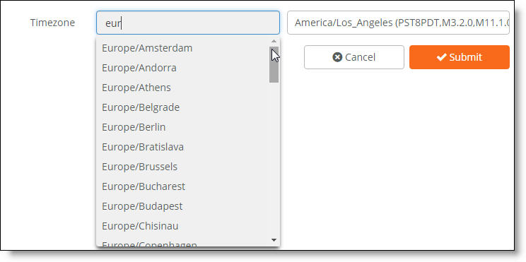
7. Select a time zone from the drop-down list.
8. Click Submit.
9. Repeat steps 2 through 8 to create additional sites one at a time: for example, factory and research lab sites.
The next step is to add tags to group sites. Tags are a powerful way to provide structure for a large number of sites and allow an additional or alternative method of grouping sites. Any sites tags that match can be grouped together. Site tags can be used to
•make creating a hub-and-spoke (Leaf mode) network topology easier.
•apply a granular firmware update policy to a group of sites.
•make bulk changes to site configurations.
To add tags to a site
1. Choose Network Design > Sites.
2. Select a site.
3. Select the Location tab.
4. After Tags, type a tag and press Enter.
A site can have none, one, or multiple tags. Repeat step 4 to add more tags.
With the site definitions complete, you can now configure the network zones and topology. See
AutoVPN modes.
To import multiple site definitions
1. Create a tabular data file in a spreadsheet or database that contains the site definitions and save it in the CSV format.
Source columns for bulk site creation

Include these columns in the CSV file:
•Short name - A unique short name for the site: for example, SV. Don’t include spaces.
•Long name - A descriptive name for the site: for example, Office SV.
•Tags - A comma-separated list of tags to group operations or filter sites, for example: Office, Development Sales. Use tags to provide structure for a large number of sites and allow an additional or alternative method of grouping sites. A site can have none, one, or multiple tags.
•Street address - The site’s street address.
•City - The site’s city.
•Country - A valid two-letter ISO country code.
•Time zone - The time zone associated with the site location: for example, American/New York. The time zone in the CSV file must match an entry on the timezone list that appears on the Create Site page. To view the timezone list, choose Network Design > Sites, click Add Site(s), and select New Site.
Valid time zones on the Create Site page
You can also define zones and uplinks in the file. If you don’t include zone and uplink definitions, you have the option of cloning preexisting zones and uplinks with site definitions after importing the file.
2. Choose Network Design > Sites.
3. Click Add Site(s) and select Bulk Site Creation.
4. Click Start: Select a CSV file and navigate to a local file.
5. Select the file and click Open.
Bulk site creation
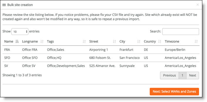
6. After the system imports the site definitions, review the site listing. To fix any problems, edit the original CSV file and reimport it. SCM will never reimport or change a site that already exists with the same short name.
7. Click Submit.
8. Click Next: Select WANs and Zones.
Optional uplink and zone selection
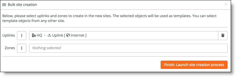
9. Optionally, select preexisting uplinks or zones to use as templates for the new sites.
When you leave the zone or uplink selection blank, the system doesn’t create any more zones or uplinks and you can add them manually later.
10. Click Finish: Launch site creation process.
The system imports the site definitions into SCM.
Bulk site creation progress
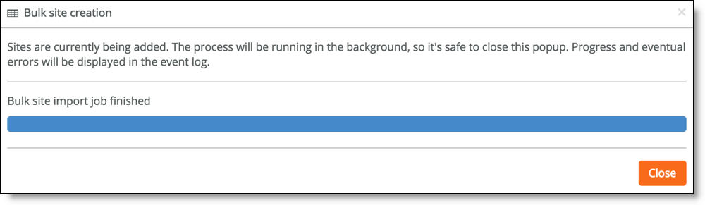
11. Click Close.
12. Select the Events tab or choose Visibility > Event Log to monitor the site creation progress in the Event log. The Event log includes any site creation errors.
Zones within a site
Zones are at the center of SteelConnect. A zone is equivalent to a Layer 2 IP segment within a site. Zones define subnets and VLANs on gateways.
Every site has at least one zone and can have multiple zones. When you create a site, SteelConnect automatically adds a default zone.
Zones can cross sites. For example, for a business application that involves a call center that requires peer-to-peer networking, you can stretch a single zone across multiple sites, providing users all over the globe with one universal security policy applied to the same IP zone.
You can add zones to any sites or any organization. A zone belongs to a site, but it can also belong to multiple sites. A site is a location like an office building, a hosting center, or a cloud location. Every site has at least one internet uplink and one local network zone.
To add a new zone to a site
1. Choose Network Design > Zones.
2. Click New Zone.
3. Select a site from the drop-down list.
4. Type a unique single word short name that describes the zone. Don’t use spaces in the name.
5. Optionally, enable the zone for guests to add some extra security and isolate the guests from other zones. Guest zones are only allowed to send traffic over to the internet.
Essentially assigning a guest zone to a site sends that traffic directly out to the internet.
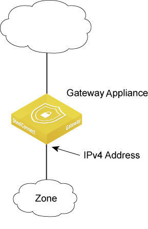
6. SteelConnect configures IPv4 addresses at the zone level. A new zone can automatically use the default IPv4 address numbering specified on the Organization > Numbering Pools tab. Specify a subnet to override the default zone numbering.
Both IPv4 and IPv6 addresses come from finite pools of numbers. Don’t create a zone with a subnet the size of the full IP address pool, because doing so can exhaust the pool. After the pool is exhausted, SteelConnect is unable to create the zones with the allocated subnets.
7. Specify the gateway IPv4 address for the network. A SteelConnect gateway will automatically configure itself with this IP address.
8. Select whether the default gateway configuration is automatic (the default setting) or manual. Select manual to use a third-party routing configuration or a centralized DHCP server.
For a manual gateway configuration, you must assign an IP address on the LAN side of the gateway to make the gateway a member of the zone.
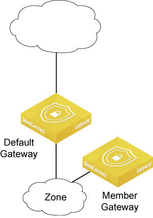
9. When there are multiple gateways in one location, select which gateway will bind to the zone as the default gateway.
10. When SCM creates new zones, it assigns the default global VLAN ID numbering specified on the Organization > Numbering pools tab.Specify a VLAN ID to override the default VLAN numbering.
11. Click Submit.
12. Repeat steps 2 through 10 to create additional zones.
Assigning a gateway to a zone
You can assign a gateway to a zone manually or automatically. By default, SCM assigns a gateway to a zone automatically.
To manually assign a gateway to a zone
1. Choose Network Design > Zones.
2. Select the zone and then select the Gateways tab.
3. Select Manual as the default gateway configuration.
4. Click Add Assignment.
5. Select the gateway.
6. Assign the gateway IPv4 address to the LAN side of the gateway to make the gateway a zone member.
7. Click Submit.
Adding a gateway to a zone manually
Assigning more than one gateway to a zone
You can assign several gateways as members in a zone, and also you can add gateways as members to remote sites. Each gateway that becomes a member of a zone can route into the zone’s network.
To manually assign more than one gateway to a zone
1. Choose Network Design > Zones.
2. Select the zone and then select the Gateways tab.
3. Select Manual as the default gateway configuration.
4. Click Add Assignment.
5. Assign a gateway to the zone.
6. Click Submit.
Adding another gateway to a zone manually
Any gateway in a zone can act as a DHCP relay, but you must configure only one gateway as a DHCP relay per zone.
Configuring a gateway as a DHCP relay agent
You can configure a gateway as a DHCP relay agent. When a gateway is configured as a DHCP relay agent, it forwards DHCP request and reply packets between DHCP clients and DHCP servers that aren’t on the same physical subnet. The DHCP relay agent gateway doesn’t have to be the default gateway.
You can specify more than one DHCP server that a gateway relays requests to. For example, if you’re using an active/passive server cluster, and each member in the cluster has a unique IP address, you can specify both IP addresses. When two DHCP servers are specified, the gateway sends the DHCP request to both servers at the same time using the different IP addresses and only the active cluster member replies.
There is no limit to how many DHCP servers you can configure.
To configure a gateway as a DHCP relay
1. Choose Network Design > Zones.
2. Select the zone in which to locate the DHCP relay.
3. Select Gateways and select Manual.
4. Edit the existing default gateway assignment or add a new gateway assignment.
5. If the DHCP server is on, turn it off.
6. Turn on the DHCP relay.
7. Specify the IPv4 address of the DHCP server or servers to use. Separate two IP addresses with a comma.
8. Click Submit.
Forwarding DHCP/BOOTP requests to a DHCP server on a remote network
Gateways typically provide dynamic IP addressing to clients; however, you might want to have the gateway forward DHCP/BOOTP requests to a central IP address management server.
To forward DHCP/BOOTP requests
1. Choose Network Design > Zones.
2. Select the zone where the clients machines will connect.
3. In the LAN panel, select the Gateways tab. Set the default gateway configuration to Manual.
4. Click Edit.
5. In the Edit gateway assignment pop-up window, set DHCP/RA Server to Off.
6. Set DHCP Relay to On.
7. Type the IP address of the DHCP server in the DHCP relay address field.
8. Click Submit.
Forwarding inbound internet traffic to a remote server
You can allow clients on the internet to access select applications on your internal network, behind your SteelConnect gateway. To do this, you create a custom application and then create an inbound rule.
To create external to internal port forwarding on a gateway
1. Choose Applications > Custom.
2. Click New Application.
3. Choose a name and description for the inbound application.
4. Select the application type Device from the drop-down list.
5. Select the destination server.
6. Choose a protocol such as TCP or UDP.
7. To only forward specific ports, set Limit TCP/UDP ports to On.
8. List the ports to be forwarded in the Ports text box. Specify ranges with a dash; separate several ports or ranges with a comma.
9. Click Submit.
10. Choose Rules > Inbound (NAT) and click New inbound rule.
11. Select the Application you created in the previous steps.
12. Choose one or more uplinks where you want to implement this rule. Leave the other values at their defaults.
13. Click Submit.
The new rule appears in the list.
Creating a third-party zone
A zone that isn’t directly connected to a SteelConnect gateway is called a third-party zone. You can create a third-party zone that is reachable by other zones. After creating a third-party zone, you add a route to make it reachable. The route includes a next hop IP address in the subnet of any of the connected networks, which is typically a third-party router.
When the uplink between the SteelConnect gateway and the third-party router (or SteelConnect gateway) are configured as BGP neighbors, the zone is advertised by the SteelConnect gateway and learned by its BGP neighbor (the third-party router or SteelConnect gateway).
For details on BGP, see
BGP.
You can create one third-party route for one zone. Multiple routes aren’t supported.
To create a third-party zone
1. Choose Network Design > Zones.
2. Click New Zone.
3. Select a site.
4. Specify the third-party zone’s primary IPv4 address.
5. Specify the third-party zone’s default gateway IP address.
IPv6 addresses are not supported.
6. Select Manual as the default gateway configuration.
7. Click Submit.
8. Select the zone you just created.
9. Select the Gateways tab.
10. Under Gateway assignments, click Delete to remove the default gateway assignment.
11. Click Confirm to delete the default gateway.
12. Select the Settings tab.
13. Under third-party routing, click Add route.
14. To add the next hop, after From Zone/Net, select any directly connected zone in the same site.
15. In the IPv4 gateway field, type the IP address of the third-party router or gateway.
16. Click Submit.
17. Verify that the zone appears as a third-party gateway route.
The SteelConnect gateway will now advertise the third-party zone in BGP and its BGP neighbor (the SteelConnect gateway or the third-party router) will learn the zone.
Integrating a third-party router/gateway into a zone
To use a third-party router/gateway as the default
1. Choose Network Design > Zones.
2. Select the zone and then select the Gateways tab.
3. Select Manual as the default gateway configuration.
4. If there’s already a gateway assigned, delete it.
5. Click Add assignment.
6. Assign the third-party router/gateway as a member gateway for the zone.
7. Click Submit.
8. Choose Network Design > Uplinks.
9. Select Settings.
10. Select DHCP or static.
11. Select Manual as the default gateway configuration.
12. Click Submit.
Turning off outbound NAT
Network Address Translation (NAT) is enabled on all uplinks by default. You can turn off outbound NAT for deployments where:
•The gateway is behind a corporate firewall that already performs NAT.
•The network is using all public IP addresses.
•The network is internal and it routes untranslated, native addresses.
•An upstream gateway, router, or firewall will perform NAT.
To turn off outbound NAT for a zone
1. Choose Network Design > Zones.
2. Select the zone and then select the Gateways tab.
3. Change the Gateway type to manual.
4. Click Edit for the current gateway, and click On to skip outbound NAT.
To turn off outbound NAT for a site
1. Choose Network Design > Sites.
2. Select the site.
3. Select the WAN/AutoVPN tab.
4. Click On to skip outbound NAT.
To turn off outbound NAT for an uplink
1. Choose Network Design > Uplinks.
2. Select the uplink.
3. Select the Settings tab.
4. Click On to skip outbound NAT.
DNS settings
By default, SteelConnect appliances use the IP address assigned to them using DHCP from the ISP’s DNS server. If the default DHCP-assigned server fails, the appliances use the public Google DNS servers.
You can use a corporate DNS server for all DNS resolution. You can also resolve internal IP addresses separately using DNS routing.
To change the DNS settings
1. Choose Network Design > Sites.
2. Select the DNS tab.
3. After Site DNS Server, type the IPv4 or IPv6 DNS server primary IP address. Separate a second DNS server IP address with a space.
4. Click Submit.
A 5030 gateway ignores site-specific DNS settings. Instead, it uses the DNS management port settings.
To view the DNS settings for a 5030 gateway
1. Select the 5030 gateway.
2. Choose Ports.
3. Select Port 1, the management port.
4. Select the Info/Mode tab.
The settings appear under Mode when Static IP is selected as the type.
DNS routing
You can use alternate DNS servers during the DNS resolution process. For example, you can configure internal DNS servers and forward queries to them for DNS lookup. Specifying multiple internal DNS servers localizes the queries, making DNS resolution more efficient. For example, you can split up the DNS resolution by forwarding all corporate DNS queries to an internal DNS server and forwarding all other queries to the ISP’s DNS servers. The queries resolve to one IP address on the internal network, and another on the external network, reducing the load on the corporate DNS server.
To direct DNS queries to specific internal DNS servers based on domain names
1. Choose Network Design > Sites.
2. Select the DNS tab.
3. Click New DNS route.
4. Type the domain for which you want to use an internal DNS server.
5. Type the IPv4 or IPv6 address of the target server to use to resolve the domain. Separate multiple IP addresses with a space. To bind a server to a specific source IP address, add /SRC to the IP address.
RADIUS authentication
You can configure an NPS/RADIUS server to use wireless authentication for a site. If a site doesn’t have its own server, it can use another site’s server.
To configure a RADIUS server
1. Choose Network Design > Sites.
2. Select the site to configure.
3. Select the RADIUS tab.
4. Click New RADIUS Server.
5. Specify the RADIUS server IP address, and, optionally, a port.
6. Specify the shared secret using this format:
sharedsecret@ipaddress[@port] (for example, sharedsecret@10.10.10.10).
7. Click Submit.
You can repeat steps 2 through 4 to add a second RADIUS server for WPA-EAP authentication if the first RADIUS server doesn’t answer within a certain time.
To set up an SSID using WPA2 Enterprise security
1. Choose WiFi > SSIDs.
2. Click New SSID.
3. Select WPA2 Enterprise from the security drop-down list.
4. Click Submit.
5. Choose WiFi > Broadcasts to begin broadcasting the Enterprise SSID at the applicable sites.
Creating a WAN
A WAN in SteelConnect is simply the WAN cloud that sites use to communicate with each other. It describes the type of transport available for application flows. SCM creates a default WAN. You might want to create additional WANs to enable path selection for failover or redundancy. Name your networks with words such as Primary MPLS or Internet.
To create a WAN
1. Choose Network Design > WANs.
2. Type the WAN name: for example, Primary or Secondary MPLS.
3. Optionally, type a longer description for the WAN and select WAN settings, described in
WAN settings.
4. Click Submit.
WAN settings
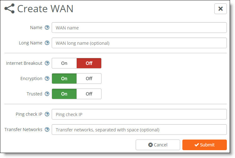
WAN settings
•Internet Breakout - Click On to break out traffic directly to the internet from this site. For a private WAN circuit without internet reachability, click Off (the default setting).
Internet NAT - (Appears when you enable Internet Breakout) Masks traffic leaving an uplink connected to an MPLS network with the uplink’s public IP address instead of using the original private source IP address. When internet NAT is on, the gateway masquerades the local packets for the entire MPLS network, including every zone.
Breakout sites - (Appears when you enable Internet Breakout) Select sites that are available to this site as an internet breakout location. Click the search selector for a list of sites directly connected to the internet. To use a third-party site as the internet breakout site, leave the list blank and the internet breakout site configured in the Network defaults tab will be used.
•Encryption - Click On to create an additional overlay network of VPN tunnels between internal zone-to-zone encrypted WAN traffic over noninternet uplinks. The default setting is on. Enabling encryption on a second WAN doubles the number of VPN tunnels on the gateway.
You can deploy an MPLS overlay that uses encryption and turn encryption off for another MPLS overlay.
When Internet Breakout is enabled and one or more breakout sites are configured, internet traffic is sent encrypted to the configured breakout sites. When encryption is on, zone-to-zone traffic is sent encrypted to the remote site.
When Internet Breakout is enabled but there isn’t a breakout site configured, internet traffic is sent unencrypted to the WAN default gateway.
•Trusted - Click On to permit all unencrypted traffic originating from a WAN to communicate into the gateway’s WAN and LAN zones. For example, enable the Trusted button to allow SteelConnect sites and legacy router sites within the WAN to communicate with each other.
Prior to SCM 2.2, to allow communication between a host originating in a native MPLS network and a specific host in the gateway LAN zone, you must create an inbound NAT rule identifying each host and allowing them to trust each other. Now, instead of creating multiple inbound rules to permit trust, simply enable the Trusted button.
When enabled, all WAN transfer networks and eBGP learned networks are allowed to communicate into the gateway LAN zones.
A transfer network is a network on the WAN side of the gateway that isn’t part of the gateway LAN zones. For details on eBGP learned networks, see
Dynamic routing overview.
•Ping check IP - Add an IP address to probe for WAN availability.
If the ping fails to that IP address, the system declares all uplinks to that WAN are down. Internet uplinks perform an automatic ICMP ping check every 10 seconds. When a ping at the 10-second interval fails, it retries three times at 1-second retry intervals.
•Transfer Networks - A transfer network is a network on the WAN side of the gateway that isn’t a part of the gateway’s WAN or LAN zones. For example, a transfer network could be used for your ISP addressing or as the core of your MPLS provider that you don’t have loaded as a zone on your gateway or inside of your organization. In this example, you can either enable it as a transfer network that polls for WAN availability using an inside IP address or you can use an IP address to poll for ISP uptime.
Creating uplinks
Uplinks define how traffic is sent from the SteelConnect gateway to the various WANs to which it has been assigned. An uplink physically connects the site to a WAN. A site can have a single uplink or multiple uplinks to the same WAN and can connect to multiple WANs. You can use multiple uplinks to the same WAN for redundancy.
You need to bind an uplink to a site and a WAN.
You cannot enable multiple uplinks on the same subnet on a gateway. This is a common restriction with routers because choosing a next hop based on overlapping subnets is ambiguous.
For details on data center uplinks on a 5030 gateway, see
Creating data center uplinks.
To create an uplink
1. Choose Network Design > Uplinks.
2. Click New Uplink.
3. Select a site. Each uplink is site-specific and its connection type differs between sites.
4. Type the uplink name: for example, primary.
5. Select a WAN.
You can enable an uplink as a backup when no other uplinks are available. See
Step 9. Uplinks that are configured for failover must be connected to the same WAN.
6. Select how the uplink connects to the WAN:
•DHCP client
•Static
•DSL/PPPoE - Configure a DSL physical layer that uses the Point-to-Point Protocol over Ethernet (PPPoE) credentials on the gateway so it can authenticate and tunnel with the internet service provider. This typically means that the customer enters a user name and password provided by the ISP to use the last-mile link from the customer premises to the ISP. The gateway then connects to the internet using NAT and routes traffic between the configured zones and the internet.
•DSL/PPPoA/PPTP
Most DSL lines have a forced reconnect imposed by the ISP, typically in a 24-hour interval. You can proactively select the disconnect and reconnect time to control when the disconnect occurs.
For example, if you switched your modem on for the first time during business hours, you’ll be stuck with a reconnect during business hours, every 24 hours, until you disconnect proactively outside of business hours. You can use the Time for PPP-reconnect setting to automate disconnects at a specified time.
To reconnect PPP uplinks at a certain time of day, select a 15-minute interval from the Time for PPP-reconnect drop-down list.
The SteelHead SD 570-SD gateway, 770-SD gateway, and 3070-SD gateway models don’t support the DSL/PPPoE or DSL/PPPoA settings for uplinks.
7. For an uplink using a static IP address, complete these fields (either IPv4 or IPv6):
•Specify a static IPv4 address. When creating an uplink to a private network, you must specify the IPv4 address with a /32 netmask.
•Specify a static IPv4 gateway.
Or
•Specify a static IPv6 address.
•Specify a static IPv6 gateway.
8. Optionally, specify a VLAN tag (1 through 4049). Note that when you specify a VLAN tag, connectivity to uplinks without a VLAN tag or uplinks that use a different VLAN tag is lost.
9. Optionally, you can enable the uplink as a backup when no other uplinks are available. This setting applies to two uplinks connected to the same WAN. When there is only one uplink and it’s set to backup only, it will be used until there is another uplink in the same WAN that is always active.
10. Click Submit.
Selecting an uplink priority
You can set an AutoVPN priority for uplinks connected to the same WAN that determines the order in which they are used. For example, when you create two uplinks and set the first uplink to high priority and set the other to normal, SCM creates a tunnel for the uplink with the highest priority.
If something happens to the high-priority tunnel, SCM reestablishes the tunnel through the uplink with the next highest priority.
When you set the same priority for both uplinks, SCM creates a tunnel for each one based on the source and destination.
To set an uplink priority
1. Choose Network Design > Uplinks.
2. Select an uplink.
3. Under AutoVPN priority, select one of these options from the drop-down list:
•Don’t use this uplink for AutoVPN - Disables AutoVPN use for the uplink.
•Low - Sets the uplink to the lowest priority.
•Normal - Sets the uplink to the normal priority.
•High - Sets the uplink to the highest priority.
4. Click Submit.
Turning off AutoVPN for an uplink
At times you might want to disable AutoVPN for an uplink. For example, you can turn AutoVPN off to bring a tunnel down for troubleshooting tunnel connectivity.
To turn off AutoVPN for an uplink
1. Choose Network Design > Uplinks.
2. Select an uplink.
3. Under AutoVPN priority, select Don’t use this uplink for AutoVPN.
4. Click Submit.
Creating an uplink for a single router to an MPLS network
To set up a VPN over the MPLS network as shown in
One router connecting to MPLS, configure the uplink of the gateway to propagate the internal IP address that the remote sites use as the endpoint target for the AutoVPN tunnel. By default, SCM uses the external IP address facing the internet.
SCM activates AutoVPN only for uplinks connecting to WANs using the internet and skips other interface types.
To configure an uplink to use an internal interface
1. Choose Network Design > Uplinks.
2. Select the uplink.
3. Select AutoVPN.
4. Select Internal Interface IPv4.
5. Click Submit.
Adding zone details
Choose Network Design > Zones and select a zone to view more configuration possibilities:
•IP tab - Define the IPv4 or IPv6 network and gateway addresses.
By default, the gateway assumes that it is the IP gateway for the site to serve DHCP addresses. Clients on the LAN side will use it as their .1 address. Use this tab to change the default gateway IP address to any other IP address in that subnet for which it’s serving DHCP addresses.
You can also enable IPv6 to allow a gateway that provides default gateway services to also send router advertisements (RAs) for IPv6 connectivity in this zone.
SteelConnect does not allow 0.0.0.0/0. Use a specific IP address and subnet mask.
To enable the gateway to send router advertisements for IPv6 connectivity in a zone
1. Click On next to Use IPv6.
2. Specify the IPv6 network.
3. Specify the IPv6 gateway IP address for the network.
4. Click Submit.
•Gateways tab - By default, a SteelConnect gateway deployed in the site is automatically configured as the default gateway for this zone. The zone uses the default gateway IP addresses specified on the IP tab. If you want to control all gateway assignments for this zone manually, or you want to use a third-party default gateway for this zone, select Manual.
•DHCP tab - When the gateway is acting as the DHCP resource for a zone, use these settings to configure its properties and parameters. You can also use the Options field to make a specific DHCP proxy server available to the SteelConnect appliances instead of using a SteelConnect gateway as the DHCP resource.
Range start - First IP address available for assignment to DHCP clients.
Range end - Last IP address available for assignment to DHCP clients.
Lease time - Sets how long a gateway acting as a DHCP server waits for a zone lease renewal before invalidating its lease. The zone must renew its IP configuration data before the lease period expires or the gateway invalidates the zone’s lease and discontinues use of its current IP address. You can select a lease renewal duration time of 5 minutes to 48 hours from the drop-down list.
Options - Specify advanced configuration options for the DHCP server. Use a separate line for each configuration option.
You can use Options to create a secure environment that prohibits direct internet access to end users or devices on an internal enterprise network. HTTP proxy support allows direct client communication and restricts direct internet access by passing all traffic bound for the SCM through an explicit proxy. The DHCP server tells the SteelConnect appliance the IP address or hostname of the HTTP proxy server. The proxy is then used to connect to SCM.
To configure an HTTP proxy for a SteelConnect appliance behind a gateway
•In the Options field, specify the vendor code Riverbed, 42, and your HTTP proxy server IP address and port number. You must enclose the IP address or hostname and port number in quotation marks:
#option vendor:Riverbed,42,“IP address or hostname:port”
This example allows the SteelConnect appliances such as gateways, switches, and access points deployed behind a SteelConnect gateway to use a proxy for all traffic destined to SCM.
Because a gateway doesn’t necessarily receive an IP address through DHCP, setting up HTTP proxy support for a gateway behind a router requires more configuration. To configure HTTP proxy support for a gateway, you need to add the vendor code to the router in front of the gateway. When you add the Riverbed vendor code to a router, one of the uplinks will request and receive the vendor code offering, install it, and then use it.
To configure an HTTP proxy for a SteelConnect gateway behind a router
•When using the ISC DHCP server for providing DNS to a SteelConnect Gateway, specify these lines in the configuration file to set the SCM proxy address:
Option space Riverbed;
Option Riverbed.proxy code 42 = text;
Option local-encapsulation code 43 = encapsulate Riverbed;
Option Riverbed.proxy "host_addr:port_no";
The HTTP proxy needs to be available on the underlay network.
Reverse SSH tunnels don’t work with HTTP proxy support.
•VLAN tag - SCM automatically assigns a VLAN ID to a zone, even if the tags aren’t used on the wire. You can change the VLAN ID.
You can reuse the same VLAN ID in different zones in multiple sites. Two zones in the same site can’t use the same VLAN ID.
When you use the same VLAN ID in different sites, you can still import a zone from another site, unless the local destination site already uses the VLAN ID of the imported zone. When there is a conflict between the VLAN ID for the imported zone and the local destination site, the local zone takes precedence and its port, gateway assignments, and broadcast settings are used. The system disables any conflicting assignments and settings and displays an alert that the zone has not been imported.
•Policy tag - Forces anything that matches a policy tag to drop into that zone. For example, you can assign certain users a policy tag, such as using tags to categorize executives into a unique zone no matter where they roam or what they plug into. You could also use a policy tag to move everyone from conference room 1 to conference room 2, or you could assign a policy tag to employees that use the same type of cubicle across the office so that they receive the same connection each time they connect to the network.
•Management zone - Designates a zone as the place that access points and switches use to receive their dynamic IP addressing when DHCP is enabled. Appliances that use multizone (VLAN trunk) connectivity will use this zone for IP autoconfiguration and console communication.
•WAN/AutoVPN - Use the internet breakout preference option to override any breakout points previously set at the site or organization level and choose a path for each zone. For example, you could set up a testing lab zone to send its traffic over the internet. You could also set up a production zone at that site to backhaul traffic through the main data center. Use the membership option to choose which WAN or AutoVPNs you want a particular breakout preference to take.
Internet traffic breakout or backhaul shows an internet breakout deployment.
Zone settings
Use the Settings tab to:
•change a zone name.
•prevent ICMP traffic from entering the zone. (ICMP traffic is always permitted to leave the zone.)
•add routes to networks with third-party routers when the SteelConnect gateway doesn’t have ownership of all the networks that touch it. For example, there might be a zone used as a transient network or an extension to another site connected to the LAN of that network.
Specify any networks with third-party routers to make the SteelConnect gateways aware of their existence and how they are reached. For example, if there is a demilitarized zone (DMZ) that is separated by a firewall, you must let the remote sites know where the DMZ is located. For details, see
Creating a third-party zone.
Adding a second IPv4 network subnet to a zone
SteelConnect lets you add additional IPv4 network subnets as part of an existing zone using the ADDL Networks tab. For example, you can mix a public IPv4 network with a private one. Any subnets added become part of RouteVPN. The difference between this feature and the third-party routes described in
Creating a third-party zone is that the SteelConnect gateway can act as the gateway for this traffic.
To make these additional network subnets reachable through a SteelConnect appliance, you must assign a gateway from the Gateways tab.
Adding a static route manually
1. Create a zone called “Remote Network” belonging to the site.
2. Reopen the zone “Remote Network” and select the Gateways tab.
3. Switch the default gateway configuration to Manual.
4. If there’s already a gateway assigned, delete it.
5. Choose Network Design > Zones.
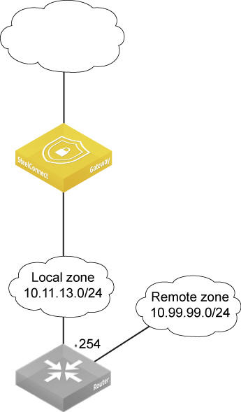
6. Select the zone that needs to be reachable through the third-party router (shown as remote zone 10.99.99.0/24 in
Gateway using a static route).
7. Select the Settings tab.
8. Click Add route.
9. In the From Zone/Net field, type the zone connected to the Riverbed gateway where the third-party gateway is located (shown as local zone in
Gateway using a static route).
10. In the IPv4 gateway field, type the IP address of the third-party router belonging to the local zone (shown as .254 in
Gateway using a static route).
Gateway using a static route
Portals
SteelConnect provides wireless user access. SteelConnect also lets you create portals to customize the user access experience, whether they are registered or guest users. You can use the bring your own device (BYOD) registration, use guest vouchers, require users to click through to accept the terms of service, or create a guest portal that is authenticated by a guest login.
To set up a BYOD registration portal, you must enable email and mobile messaging (SMS) as additional authentication to join and register a device using the portal.
To configure a guest portal
1. Choose Network Design > Portals.
2. Click New Portal.
3. Select the portal type Guest Portal - Authenticated.
4. Click Submit.
After creating the portal, you need to assign it to a WiFi broadcast.
To assign a portal to a WiFi broadcast
•Choose WiFi > Broadcasts > Portal.
Registering guest devices using social media
When the portal is active on a guest zone, guests can use these methods to register guest devices:
•Mobile phone number (via SMS)
•Email address
•Social media apps Facebook, Google, and Twitter
The Organization > Social Media tab is where an administrator configures guest access using a social media app.
After guest devices are registered and validated, they are allowed access to the guest zone. Remember, guest zones are only allowed to send traffic over to the internet. Also, after you create a guest zone you can’t change it to a standard zone.
To use Facebook
1. Log in to https://developers.facebook.com. You might need to verify your Facebook account.
2. Choose My Apps > Add a New App.
3. Select basic setup instead of selecting a platform.
4. Choose a clear display name such as Riverbed Social WiFi.
5. Choose a namespace such as riverbedsocialwifi.
6. Choose a category.
7. Click Create App ID.
After successful creation, the app is in development mode and is therefore publicly not available. You must enter a valid contact email to make the app available to all users.
8. Choose Settings > Basic > Contact Email and enter a valid email address.
9. Click Save Changes.
10. Go to the menu App Review.
11. Click Yes to switch on public access.
12. Confirm that you want to make the app public.
13. Choose Settings > Advanced > Security > VClient OAuth redirect URIs.
14. Insert the redirect URL displayed in your SCM (for example, https://<mycc>.riverbed.cc/portal-social-in). You can find the redirect URL under Organization > Social Media Apps.
15. Save your changes.
In the Facebook developers sidebar, choose Dashboard and copy/paste App ID and App Secret to your Organization > Social Media Apps > Facebook Application ID/secret.
To use Google
1. Log in to https://console.developers.google.com/project.
2. Click Create Project.
3. Type a representative project name. For example, Riverbed Social WiFi.
To use a different project ID as the project name, click Edit and change the ID information.
4. Click Create.
5. Go to the Google Developers Console at https://console.developers.google.com/project.
6. Select your project: in this example, Riverbed Social WiFi.
7. To activate the Google+ API choose API Manager > Social APIs in the sidebar on the left.
8. Click Google+API.
9. Click Enable.
10. Select the OAuth consent screen tab and assign credentials to your project.
11. Select a product name to show to users: for example, Riverbed Social WiFi.
The Homepage URL, product logo, privacy policy URL, and terms of service URL are optional.
12. Click Save to store your progress.
13. In the left sidebar, choose APIS & AUTH > Credentials.
14. Click Create credentials and choose OAuth Client ID.
15. Choose a name. For example, Riverbed Social WiFi.
16. Copy the redirect URI: for example, https://<mycc>.riverbed.cc/portal-social-in.
To find your redirect URL, choose Organization > Social Media. The URL appears under access parameters.
17. Click Create Client ID and copy the client ID and secret that appear in the pop-up window.
18. In SCM, choose Organization > Social Media and then copy and paste the Google client ID and secret.
19. Click Submit.
To use Twitter
1. Sign in to https://apps.twitter.com.
2. Click Create New App.
3. In the application details, type a clear application name. For example, Riverbed Social WiFi.
4. Add an application description. For example: Twitter OAuth.
5. Add your company website. For example, http://www.riverbed.com.
6. Insert a callback URL. For example, https://<mycc>.riverbed.cc/portal-social-in. To find the callback URL in SCM, choose Organization and select the Social Media tab. The URL appears under the Social Media Apps access parameters.
7. Agree to the developer rules.
8. Create your Twitter application and copy the API key and secret.
9. In SCM, choose Organization > Social Media, and then paste the Twitter API key and secret.
10. Click Submit.