Replacing Memory Modules
This section describes how to remove and replace memory modules in the SteelFusion Edge appliances. This section includes the following procedures:
Replacing Memory Modules in 1U SteelFusion Edge Appliances
This section describes how to replace memory modules in SteelFusion Edge 2100 and SteelFusion Edge 2200 appliances. When replacing memory in the appliances, install the memory in the same slots.
The following diagram shows memory module slot locations in these appliances. (
Figure: Memory Module Slot Locations in 1U SteelFusion Edge Appliances.)
Figure: Memory Module Slot Locations in 1U SteelFusion Edge Appliances
To replace the memory modules in the 1U SteelFusion Edge appliances
1. Power down the appliance.
2. Remove the chassis cover.
Figure: Removing PCIe Carrier Locking Screws
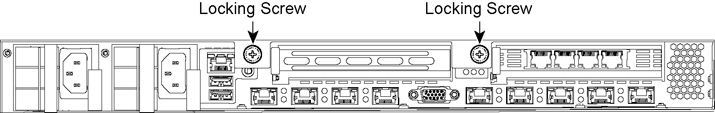
Figure: Removing PCIe Carrier
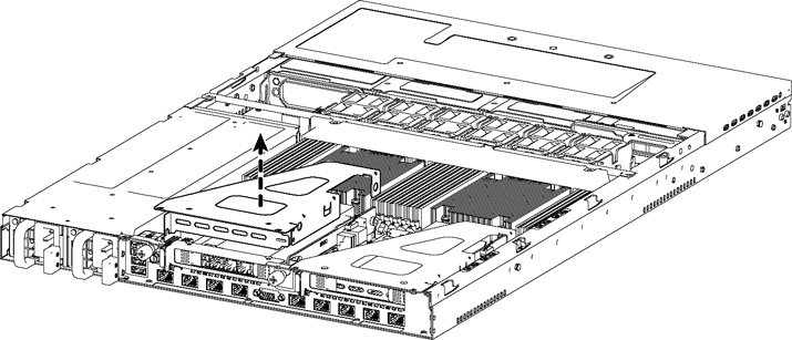
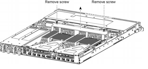
Figure: Removing Cooling Shroud Screws
Caution: 
Lift the shroud straight up to avoid damaging any components of the appliance.
Figure: Accessing the Memory Modules
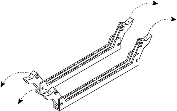
7. Remove the existing memory module and replace it with an approved memory module of the same size.
8. Align the memory-module edge connector with the slot alignment keys and insert it into the slot.
Figure: Inserting the Memory Modules into the Connector Slot and Securing
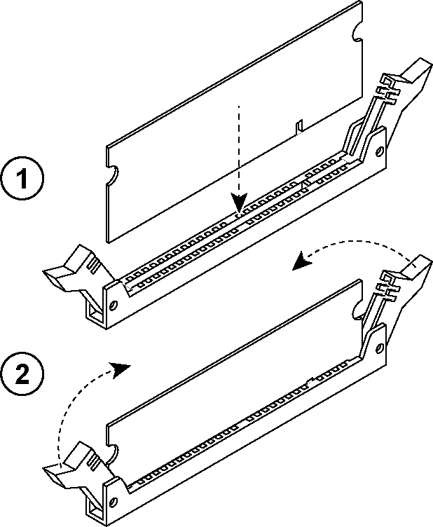
9. Press down on the memory module with your thumbs until you hear it click.
10. Ensure that all ejector tabs are in the upright locked position.
11. If necessary, replace the PCIe carrier.
12. Reinstall the cooling shroud.
13. Reinstall the chassis cover.
14. Reinstall the power cords and peripherals.
15. Power on the appliance.
Replacing Memory Modules in 2U SteelFusion Edge Appliances
This section describes how to replace memory modules in the SteelFusion Edge 3100, SteelFusion Edge 3200, and SteelFusion Edge 5100 appliances. When replacing memory in the appliances, install the memory in the same slots.
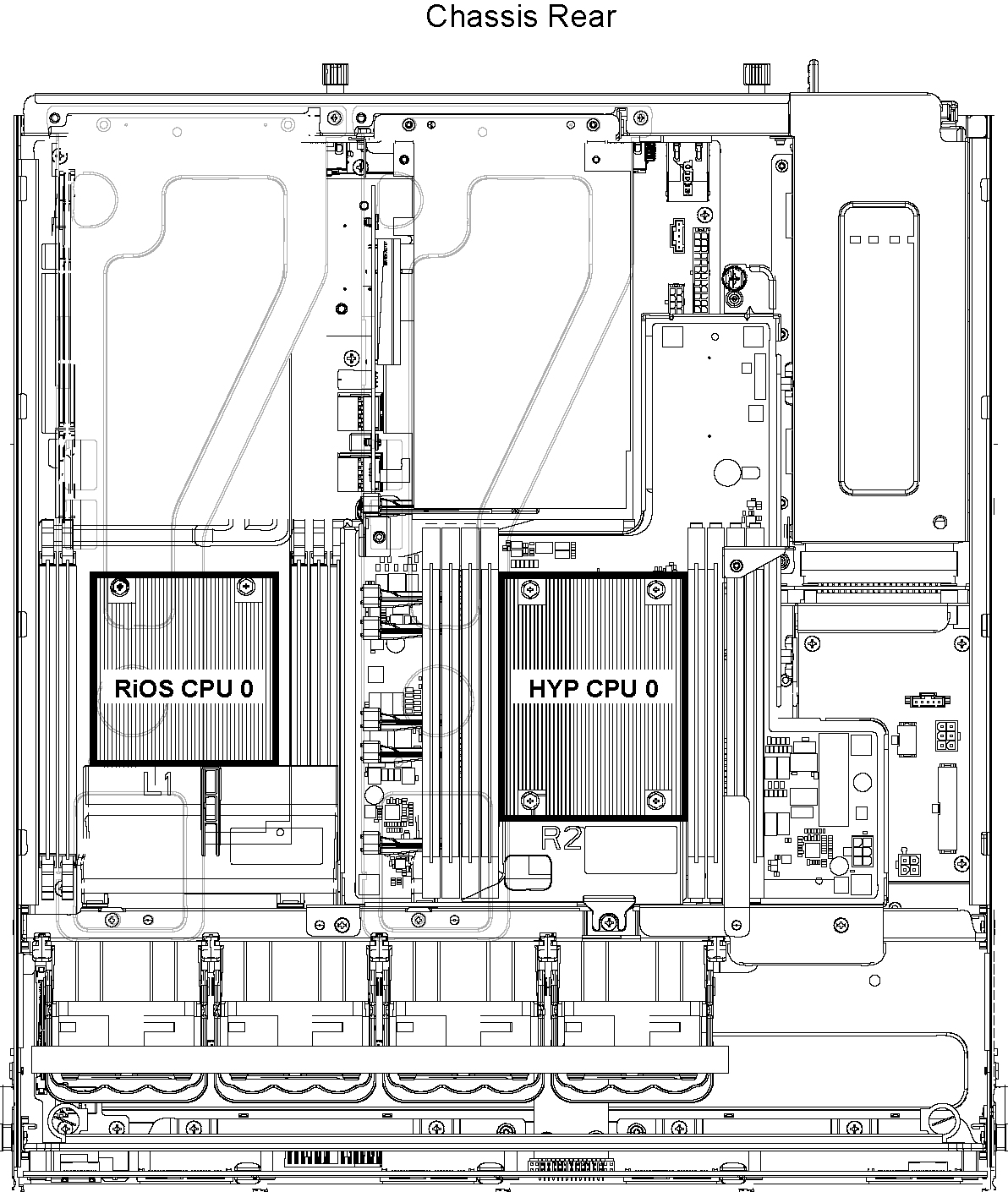
The following diagram illustrates memory module slot locations in these appliances. (See
Figure: Memory Module Slot Locations in 2U SteelFusion Edge Appliances.)
Figure: Memory Module Slot Locations in 2U SteelFusion Edge Appliances
To replace memory modules in a 2U SteelFusion Edge appliance
1. Power down the appliance.
2. Remove the chassis cover.
3. To release the PCIe carrier, remove the two locking screws on the top of the carrier (see
Figure: Locking Screws) and the one locking screw on the rear panel.
Figure: Locking Screws
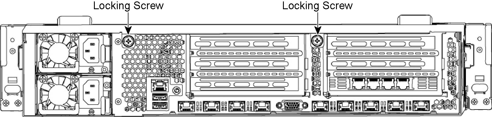
Figure: Removing the PCIe Carriers from the Chassis
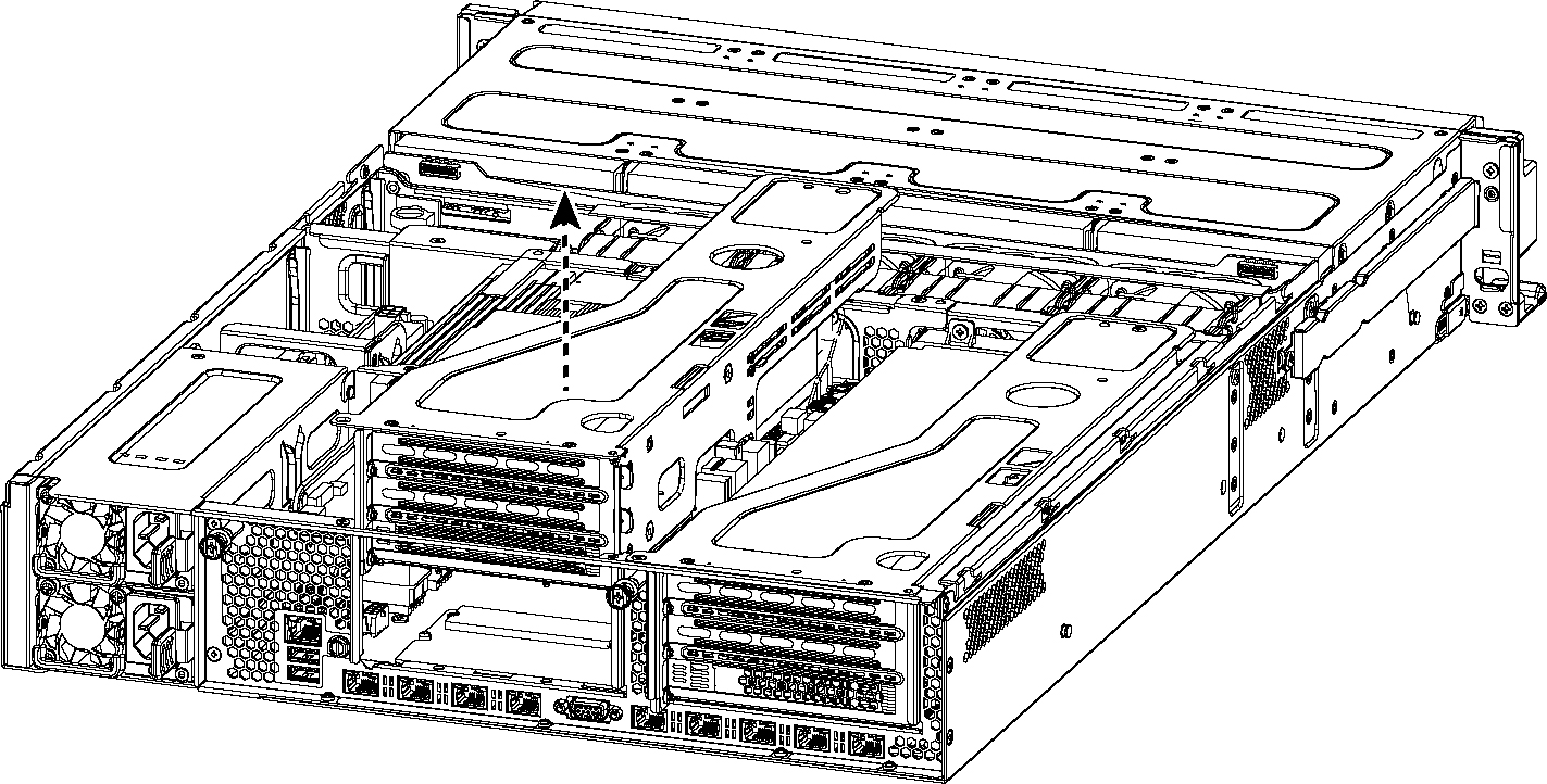
Figure: Removing Cooling Shroud
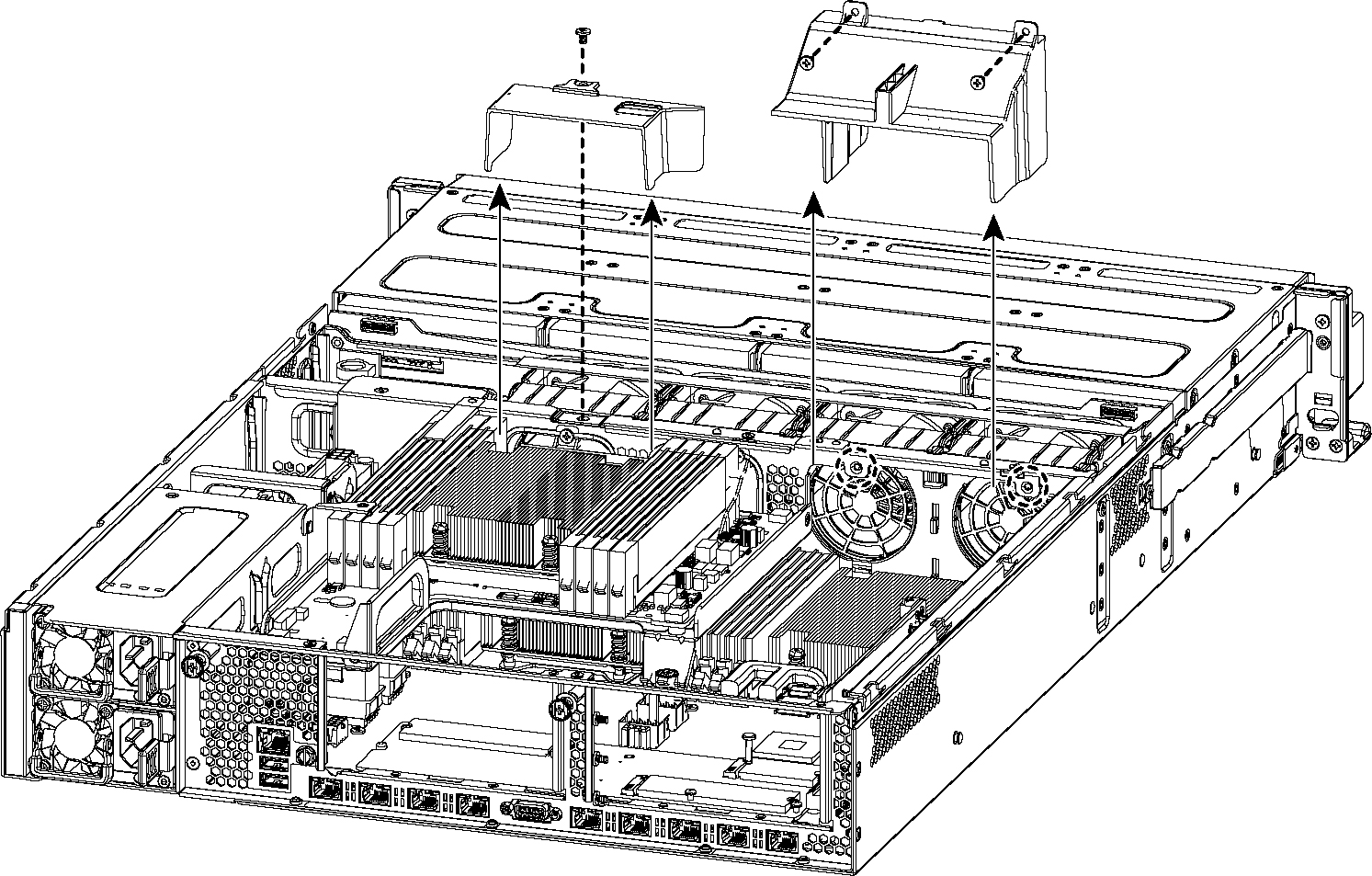
Caution: Be careful not to damage any surrounding components when removing and installing the cooling shroud. Lift the shroud straight up to avoid damaging any components of the appliance.
Figure: Accessing the Memory Modules
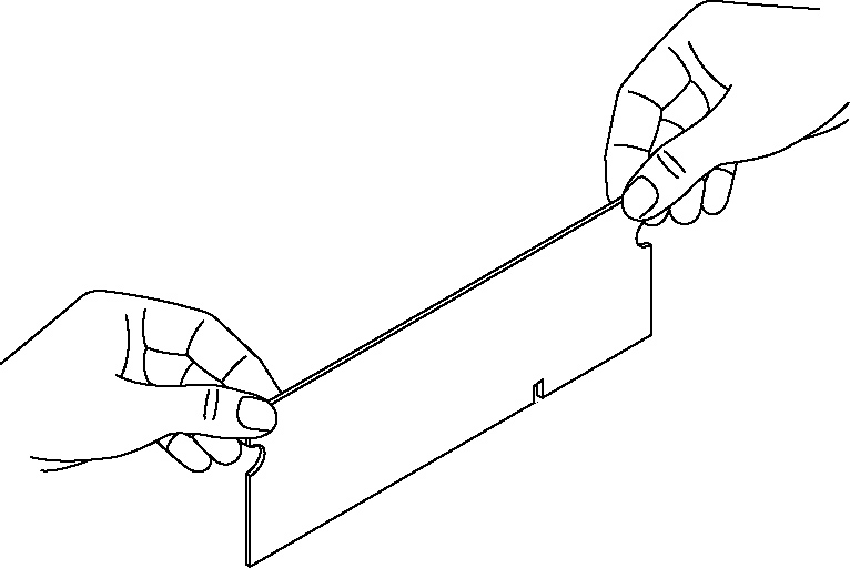
Figure: Proper Handling of the Memory Module
8. Remove the existing memory module and replace it with an approved memory module of the same size. When adding memory, always replace the memory in the black slots first. Make sure the memory is equally distributed on both sides.
Note: Replacing the existing memory module with a module of a different size is not recommended. Replace the failed memory module with the same memory module size. You must use approved memory modules. Contact Riverbed Support at https://support.riverbed.com to obtain the correct memory modules.
Figure: Inserting the Memory Modules into the Connector Slot and Securing
10. Press down on the memory module with your thumbs while pulling up on the ejectors with your index fingers to lock the module into the slot.
11. Ensure that all ejector tabs are in the upright locked position.
12. Repeat
Step 6 to
Step 11 to install the remaining memory modules.
13. Reinstall the cooling shroud.
14. Reinstall the chassis cover.
15. Plug in the power cords and the peripherals.
16. Power on the appliance.
To replace memory modules in a 2U SteelFusion Edge appliance with the QPI module installed
1. Power down the appliance.
2. Remove the chassis cover.
3. To release the PCIe carrier, remove the two locking screws on the top of the carrier (see
Figure: Locking Screws) and the one locking screw on the rear panel.
Figure: Locking Screws
Figure: Removing the PCIe Carriers from the Chassis
Note: Use extreme care when removing the QPI module. Damage to the module can cause unexpected results.
5. Remove the two small cooling shrouds by flipping them up and off of the module.
6. Disconnect the power to the QPI module.
7. Unscrew the four screws on the QPI module. There are two on the top, one in the middle, and one at the bottom of the QPI module.
8. Carefully lift the QPI module up and remove it from the appliance.
Figure: Removing Cooling Shroud
Caution: Be careful not to damage any surrounding components when removing and installing the cooling shroud. Lift the shroud straight up to avoid damaging any components of the appliance.
Figure: Accessing the Memory Modules
Figure: Proper Handling of the Memory Module
12. Remove the existing memory module and replace it with an approved memory module of the same size. When adding memory, always replace the memory in the black slots first. Make sure the memory is equally distributed on both sides.
Note: Replacing the existing memory module with a module of a different size is not recommended. Replace the failed memory module with the same memory module size. You must use approved memory modules. Contact Riverbed Support at https://support.riverbed.com to obtain the correct memory modules.
Figure: Inserting the Memory Modules into the Connector Slot and Securing
14. Press down on the memory module with your thumbs while pulling up on the ejectors with your index fingers to lock the module into the slot.
15. Ensure that all ejector tabs are in the upright locked position.
16. Repeat
Step 6 to
Step 11 to install the remaining memory modules.
17. Reinstall the cooling shroud.
18. Reinstall the QPI module.
19. Connect the power wires for the QPI module.
20. Reinstall the small cooling shrouds.
21. Reinstall the chassis cover.
22. Plug in the power cords and the peripherals.
23. Power on the appliance.