Cisco Intelligent Traffic Director and SteelHead
This chapter describes details about deploying SteelHead in a virtual in-path mode with Cisco Intelligent Traffic Director (ITD). It includes these sections:
Background and introduction to Intelligent Traffic Director
In the past, it was possible to use Policy Based Routing (PBR) or Web Cache Communication Protocol (WCCP) to redirect traffic towards one or more SteelHeads configured in a "virtual inpath" mode. This was typically a deployment architecture used in the data center, but would work just as well in branch locations. Such deployments avoid a true "in-path" deployment, yet still provide scalability and resiliency when using multiple SteelHeads in a cluster.
Although PBR is a feature available on many different vendors network products, WCCP is generally considered as proprietary to Cisco products.
With the Cisco Nexus platform (5k/6k/7k/9k series), WCCP is no longer an option. It has been replaced with a new feature known as Intelligent Traffic Director (ITD). This feature is considered to be far more flexible than WCCP but is based largely on the principals behind PBR.
The underlying mechanisms associated with the traffic redirection element of ITD in Nexus switches still use PBR configuration settings and the related software code. As the ITD configuration and commands are applied to a Nexus switch, the relevant PBR settings are automatically created. With the appropriate access level in the Nexus CLI, you can review the PBR settings.
ITD provides the opportunity for much greater throughput, weighted load-balancing, support for both IPv4 and IPv6, and many other capabilities compared to its predecessor. Within a Nexus switch, ITD operates as a service. More than one service can be configured within a single switch.
For details on ITD, consult documentation such as the Cisco Nexus 7000 Series NX-OS Intelligent Traffic Director Configuration Guide at https://www.cisco.com/c/en/us/td/docs/switches/datacenter/sw/nx-os/itd/configuration/guide/b-Cisco-Nexus-7000-Series-Intelligent-Traffic-Director-Configuration-Guide.html.
Intelligent Traffic Director concepts
This section describes a number of concepts, terms, and configuration settings related to Cisco Intelligent Traffic Director on Nexus switches. It includes these topics:
For detailed information, refer to the relevant Cisco documentation for your model of Nexus switch.
Redirection scenarios
ITD supports a number of redirection scenarios:
• Server load-balancing - Client application requests are load-balanced across multiple servers (nodes). ITD may be configured with "direct server return" (DSR) such that servers respond directly back to clients without involving ITD.
• Services load-balancing and/or clustering - Used for firewalls, IDS, IPS, WAN opt, and so on.
• Traffic steering and redirection - Used for Web Proxy and Web Cache devices.
Using ITD with SteelHeads requires ITD to be configured in the "services load-balancing" mode.
The remainder of the configuration on the Nexus switch in such a deployment is fairly straightforward and some examples are described later in this document.
ITD device groups
Device groups are simply a list of IP addresses for nodes that the ITD service uses to redirect traffic towards. In the case of a SteelHead deployment, the node IPs are the in-path addresses of the SteelHeads that are configured for virtual in-path. This means that for a SteelHead with two or more in-path interfaces configured and enabled, each interface is a node. Therefore it is possible to have designs where ITD can redirect traffic to multiple SteelHeads via multiple in-path interfaces providing scale as well as resiliency at both the network interface level and the appliance level.
In a device group where multiple device nodes are defined, you can assign a "weight" to each node. The weight is a numerical value between 1 and 256. This value enables ITD to direct more or less traffic to each node in the group depending on the weight value of each node relative to another node in the group. For example, in a device group with two nodes, one with weight 22 and the other with weight 44, the latter node will receive twice as much traffic. If no weight value is specified for a node, the value defaults to 1. If there is no weight value specified for any node in the group, all nodes are considered equal.
Also included in the device group setting is the node down detection protocol, known as a probe. This is used for checking the availability of the node(s) in the group. The following protocols are available to choose: ICMP, TCP, UDP, HTTP, and DNS. With SteelHead deployments, an ICMP probe is sufficient, but TCP probes can also be used. Because an active in-path interface of a SteelHead listens by default on TCP:7800, it will respond to an ITD probe that is configured in the device group for probe tcp port 7800. This means that if the SteelHead optimization service is stopped, or the SteelHead has entered Admission Control, it will stop responding to ITD probes on TCP:7800. This would allow for a more accurate failure scenario.
The use of buckets
Buckets are mapped to a node and the number of buckets must be a power of 2. In a SteelHead deployment, the number of buckets should always be greater than the number of nodes. This ensures the best possible chance for even traffic flow distribution between all nodes in the device group. For example, a device group that has five nodes must have a minimum of eight (23) buckets. This is because four (22) buckets would be less than the number of nodes in this example. The buckets are divided among all nodes and assigned in a round-robin manner.
If a node in a device group is configured with a weight value, then this affects the number of buckets mapped to the node. A higher weight value means more buckets are assigned compared to other nodes in the group with a lower weight value.
If there are a small number of nodes (for example 5), then it is a good idea to increase the number of buckets compared to a device group that has a large number of nodes.
According to Cisco documentation, ITD supports up to 256 nodes; however, refer to the relevant Cisco documentation for your model of Nexus switch, as this number may be different.
As the number of buckets used increases, so does the number of TCAM entries on the Nexus switch. The size of the TCAM varies between different models of Nexus switch; therefore, consult the relevant documentation for your model.
During a node failure scenario, buckets will be reassigned to one or more surviving nodes if a "failaction" setting is configured in the ITD service. For more details on failaction, see
Failaction behavior.
Probes
You can configure probes at the device-group level or at the node level. With node-level probing, each node can be configured with its own probe, allowing for further customization per node. Node-level probes are useful in scenarios where each node needs to be monitored differently for failure conditions.
By default, probes are sent at 10-second intervals simultaneously to all nodes. The probe interval can be configured down to a minimum value of 1 second. As long as the node responds within a specified timeout period, the ITD service considers the node as up and continues to redirect traffic to it. Probes continue at 10-second intervals, until there is no response to a probe, when a specified number of retry probes are sent. If there is still no response from the node after all retries have been sent, Nexus changes the node state from up to failed and marks the node status as "PROBE_FAILED." The ITD service for the device group with the failed node then performs a series of tasks to search for another node to reassign the failed traffic.
After failure, probes continue to be sent to the failed node at the configured interval. Once the node returns and starts to respond to the probes, ITD marks the state as up and traffic is reassigned back to the node.
You can also configure the probe timeout and number (count) of retries. There are two retry count settings: one for node down and the other for node up. Changing these values determines the length of time before a node is declared as failed or returns online.
For example, if the timeout is 5 seconds and the retry down count is three, then if there is no response to a probe after 5 seconds, a second probe is sent. If, after a further 5 seconds there is still no reply from the node, a third probe is sent. If there is still no reply, after another 5 seconds, the node state is "failed." In this example, failure detection is a total of 15 seconds. During this time, the ITD service continues to send traffic to the node even though the node may have already failed. Therefore, it is important to decide what the maximum overall interval should be for failure detection and subsequent traffic flow reassignment.
For a complete list of the default probe related settings, consult the documentation for your model of Nexus.
Access Control Lists
The format of the access control list (ACL) configuration on the Nexus switch is relatively unchanged from that on any other Cisco predecessor to the Nexus. It is comprised of "permit" and/or "deny" entries that optionally include a combination of network/host IPs, masks, ports, and message types.
ITD service configuration parameters
Intelligent Traffic Director runs as a service within the Nexus platform. You can have more than one ITD service running at a time. Each service instance generates a single route map
The ITD service configuration is where the correlation exists between the following parameters:
• Device group
• Network interface(s) for ingress traffic
• Failaction behavior
• Load-balance method
• Access-list
More details about each parameter are provided in the next sections.
Device group
This is the name of the device group that the ITD service instance applies to.
Network interface(s) for ingress traffic
Interfaces can be specified as physical ports or VLAN IDs. Multiple ingress interfaces can be specified for the same ITD service. If the deployment includes the use of VRFs, then all ingress interfaces and device group nodes must belong to the same VRF for the ITD service to redirect traffic.
Failaction behavior
This setting determines how traffic flows are reassigned in the event that a node failure is detected. There are several options to this setting, and they are briefly described here. Consult the relevant Nexus documentation for more details.
• Node reassign - All traffic for failed node is reassigned to the first active node on the list. When failed node returns, traffic is automatically diverted back.
• Node least-bucket - Failed node buckets are reassigned to an active node that currently has the least number of buckets already assigned. If all active nodes have the same number of buckets, then the next node in numerical order is reassigned all the buckets from the failed node. When the failed node returns, buckets are reassigned once more, and traffic is automatically diverted back.
• Bucket distribute - An algorithm internal to ITD is used to evenly assign and distribute buckets between each active node. In the event of a node failure, buckets are reassigned and traffic for the failed node is distributed across the remaining nodes as evenly as possible, although truly even distribution is not guaranteed. When the failed node returns, buckets are reassigned once more, and traffic is automatically diverted back.
You can also specify one or more hot-standby nodes. Standby nodes are specified in the device group and if there is more than one, they form a pool of standby nodes. In the event that the ITD service detects a node failure, it automatically redefines a standby node from the pool as active and starts redirecting traffic from the failed node to this node. When the failed node returns, traffic is automatically redirected back to the active node and the hot-standby is returned to the pool. If no standby node is available, or no hot-standby has been configured, then ITD reverts to following whatever "failaction" setting exists for the group.
If no hot-standby or failaction is specified, traffic is automatically passed through with no redirection.
In terms of timing, from the moment when a node down is detected, to then having traffic redirected, hot-standby is considered to be the quickest, followed by node reassign, then least-bucket, and lastly bucket distribute being the slowest. However, all failaction options are comparatively fast, completing in a matter of milliseconds.
Load-balance method
The load-balancing method specifies the use of source or destination IP address. The IP addresses themselves are derived from the access control lists. Flow symmetry is maintained between forward and return flows by reversing the load-balancing parameter in each of two separate ITD service configurations.
Access-list
The access-list setting simply specifies of the name of the access control lists (ACLs) that are defined in the Nexus configuration.
Advantages and disadvantages of ITD
In general, deployments where SteelHeads are physically in-path require less initial and ongoing configuration and maintenance than out-of-path or virtual in-path deployments. Physical in-path SteelHeads are placed at the points in your network where data already flows. Thus, with in-path deployments you do not need to alter your existing network infrastructure.
Virtual in-path techniques, such as ITD, require more time to set up because the network infrastructure must be configured to redirect traffic to the SteelHeads.
ITD has the following advantages:
• No rewiring required - You do not need to move any wires during installation. At large sites with multiple active links, you can adjust wiring by moving individual links one at a time so that traffic can then be redirected by ITD towards the SteelHeads.
• An option when no other is available - At sites where a physical in-path deployment is not possible, ITD might achieve the integration you need. For example, if your site has a WAN link terminating directly into a large access switch, there is no place to install a physical in-path SteelHead.
ITD has the following disadvantages:
• Network design changes required - ITD deployments with multiple routers can require significant network changes.
• Hardware and NX-OS upgrades required - To avoid hardware limitations and NX-OS issues, you must keep the Cisco platform and NX-OS revisions at the current minimum recommended levels. Otherwise, it might be impossible to create a stable deployment, regardless of how you configure the SteelHead. For future NX-OS feature planning, you must consider compatibility with ITD.
• Additional evaluation overhead - It can take more time to evaluate the integration of the SteelHeads. This overhead is in addition to evaluating SteelHead performance gains. You might need Riverbed Professional Services to test and perform network infrastructure upgrades before any optimization can be performed, especially when ITD is deployed at numerous sites.
• Additional configuration management - You must create access control lists and ITD configurations, and then manage them on an ongoing basis. At small sites, it might be feasible to redirect all traffic to the SteelHeads. However, at larger sites, access control lists might be required to ensure that traffic that cannot be optimized (for example, LAN-to-LAN traffic) is not sent to the SteelHeads.
Configuration of ITD deployments
This section describes how to configure for ITD and provides some example deployments. This section includes these topics:
Basic steps for configuring ITD deployments
This section describes the basic steps to set up a deployment using SteelHead and ITD.
Before you perform these steps on the SteelHead, make sure that simplified routing is set to None and connection forwarding is enabled. Virtual in-path deployments are not compatible with simplified routing.
To perform the basic steps to configure ITD
1. Configure the SteelHead as an in-path device by enabling in-path support and L4/WCCP/PBR support.
You can use the in-path enable and in-path oop enable commands, or you can use the In-Path Settings on the Network Services > General Service Settings page.
In-Path Settings
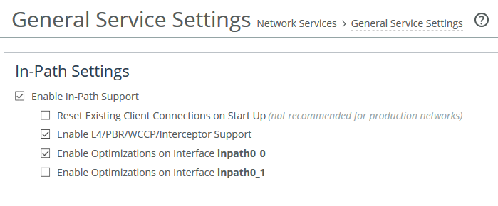
The figure above is for guidance purposes only. Depending on the model of SteelHead, the in-path interface numbering may be different to that shown here.
For details, see the SteelHead Installation and Configuration Guide.
2. Enable ITD on the Nexus switch by creating a service instance on the Nexus switch.
3. Set the Nexus switch to use ITD to redirect traffic to the ITD SteelHead.
4. Attach the desired SteelHead in-path WAN interface to the network. The WAN interface must be able to communicate with the Nexus switch on which ITD is configured and where ITD redirection takes place.
Configuring a simple ITD deployment
The design shown is a simple deployment with a single Nexus switch and a single SteelHead.
Simple ITD deployment
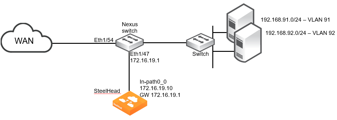
The example design includes the following:
• The SteelHead wan0_0 interface is directly attached to the Nexus switch.
• The Nexus switch is running a minimum of NX-OS release 7.0(3)I7(6).
• The SteelHead Primary interface is not shown.
• Additional networking equipment (such as router, firewall, and so on) that may exist between the Nexus switch and WAN is not shown.
SteelHead configuration
The SteelHead configuration for the example shown in the figure above is a standard virtual in-path deployment scenario. The following commands provide the basic settings:
steelhead > enable
steelhead # configure terminal
steelhead (config) # interface inpath0_0 ip address 172.16.19.10 /24
steelhead (config) # ip in-path-gateway inpath0_0 172.16.19.1
steelhead (config) # in-path enable
steelhead (config) # in-path oop enable
steelhead (config) # write memory
steelhead (config) # restart
Nexus configuration
Given the design illustrated above, the following commands can be used to enable and configure ITD on the Nexus switch:
switch(config)# feature itd
switch(config)# itd device-group RB-DC
switch(config-device-group)# node ip 172.16.19.10
switch(config-device-group)# probe icmp
Note: As described in the "ITD device groups" section, the "probe icmp" command can be replaced with "probe tcp port 7800"
switch(config)# itd branch-to-dc
switch(config-itd)# device-group RB-DC
switch(config-itd)# ingress interface Eth1/54
switch(config-itd)# load-balance method src ip buckets 16
switch(config-itd)# access-list branch-to-dc
switch(config-itd)# no shut
switch(config)# itd dc-to-branch
switch(config-itd)# device-group RB-DC
switch(config-itd)# ingress interface Vlan91
switch(config-itd)# ingress interface Vlan92
switch(config-itd)# load-balance method dst ip buckets 16
switch(config-itd)# access-list dc-to-branch
switch(config-itd)# no shut
switch(config)# ip access-list branch-to-dc
switch(config-acl)# 10 permit tcp <client-subnets> 192.168.0.0/16
switch(config-acl)# exit
switch(config)# ip access-list dc-to-branch
switch(config-acl)# 10 permit tcp 192.168.0.0/16 <client-subnets>
switch(config-acl)# exit
For more details on the Nexus commands and syntax, consult the relevant documentation for your model of Nexus switch.
Configuring an ITD high availability deployment
To be able to support greater optimization throughput capacity beyond a single SteelHead and/or provide levels of redundancy/resiliency, multiple interfaces can be used on the same SteelHead and more importantly, multiple SteelHeads can be used.
This section describes these configuration examples:
In theory, a comprehensive ITD deployment would, by design, avoid asymmetry in the traffic redirected to a cluster of SteelHeads. But Riverbed’s best practice is to ensure that Connection Forwarding is enabled between SteelHeads in a cluster to handle any possible asymmetry that may occur in the traffic flows.
At the same time, neighbor failure should be set to "Allow."
Single SteelHead with interface high availability
The design shown in this figure is a deployment with two Nexus switches and a single SteelHead with two in-path interfaces configured. This design ensures that traffic can still be accelerated in the event of a network link, Nexus switch, or SteelHead interface failure. This design does not provide SteelHead high availability.
ITD with SteelHead interface high availability
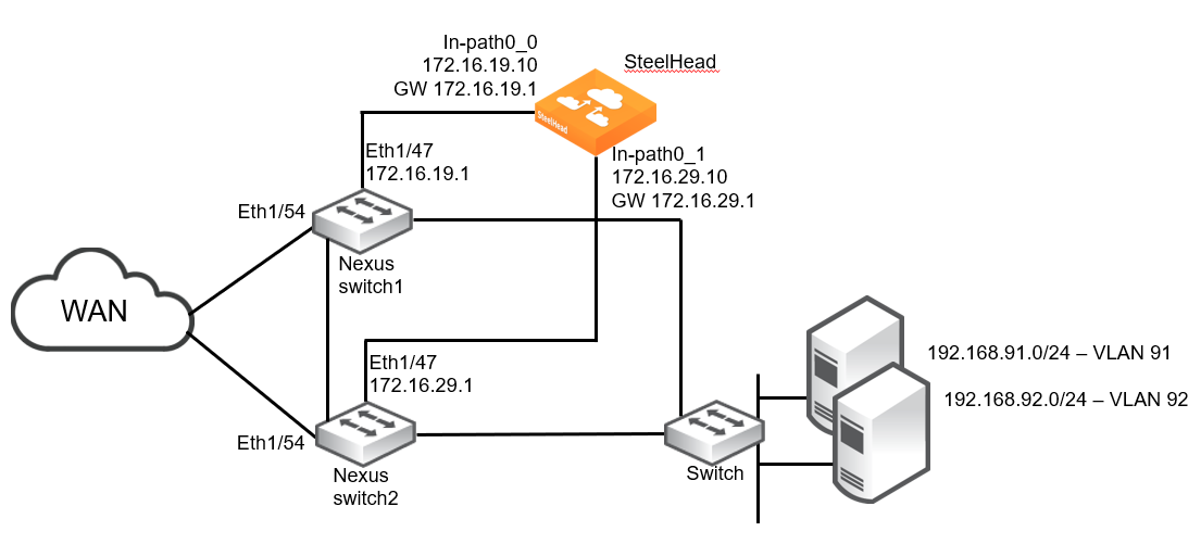
The example design includes the following:
• The SteelHead wan0_0 interface is directly attached to the Nexus switch1.
• The SteelHead wan0_1 interface is directly attached to the Nexus switch2.
• The Nexus switch1 can redirect traffic to SteelHead in-path0_1 via its interconnect to the Nexus switch2.
• The Nexus switch2 can redirect traffic to SteelHead in-path0_0 via its interconnect to the Nexus switch1.
• The Nexus switches are running a minimum of NX-OS release 7.0(3)I7(6).
• The SteelHead Primary interface is not shown.
• Additional networking equipment (such as router, firewall, and so on) that may exist between the Nexus switches and WAN is not shown.
SteelHead configuration
The SteelHead configuration for the example shown in the figure above is a standard virtual in-path deployment scenario with multiple in-path interfaces. The following commands provide the basic settings:
steelhead > enable
steelhead # configure terminal
steelhead (config) # interface inpath0_0 ip address 172.16.19.10 /24
steelhead (config) # ip in-path-gateway inpath0_0 172.16.19.1
steelhead (config) # interface inpath0_1 ip address 172.16.29.10 /24
steelhead (config) # ip in-path-gateway inpath0_0 172.16.29.1
steelhead (config) # in-path enable
steelhead (config) # in-path oop enable
steelhead (config) # write memory
steelhead (config) # restart
Nexus configuration
Given the design illustrated above, the following commands can be used to enable and configure ITD on the Nexus switch1:
switch1(config)# feature itd
switch1(config)# itd device-group RB-DC
switch1(config-device-group)# node ip 172.16.19.10
switch1(config-device-group)# node ip 172.16.29.10
switch1(config-device-group)# probe icmp
Note: As described in the "ITD device groups" section, the "probe icmp" command can be replaced with "probe tcp port 7800"
switch1(config)# itd branch-to-dc
switch1(config-itd)# device-group RB-DC
switch1(config-itd)# ingress interface Eth1/54
switch1(config-itd)# load-balance method src ip buckets 32
switch1(config-itd)# access-list branch-to-dc
switch1(config-itd)# no shut
switch1(config)# itd dc-to-branch
switch1(config-itd)# device-group RB-DC
switch1(config-itd)# ingress interface Vlan91
switch1(config-itd)# ingress interface Vlan92
switch1(config-itd)# load-balance method dst ip buckets 32
switch1(config-itd)# access-list dc-to-branch
switch1(config-itd)# no shut
switch1(config)# ip access-list branch-to-dc
switch1(config-acl)# 10 permit tcp <client-subnets> 192.168.0.0/16
switch1(config-acl)# exit
switch1(config)# ip access-list dc-to-branch
switch1(config-acl)# 10 permit tcp 192.168.0.0/16 <client-subnets>
switch1(config-acl)# exit
The configuration settings for the Nexus switch2 are identical:
switch2(config)# feature itd
switch2(config)# itd device-group RB-DC
switch2(config-device-group)# node ip 172.16.19.10
switch2(config-device-group)# node ip 172.16.29.10
switch2(config-device-group)# probe icmp
As described in
ITD device groups, the
probe icmp command can be replaced with
probe tcp port 7800.
switch2(config)# itd branch-to-dc
switch2(config-itd)# device-group RB-DC
switch2(config-itd)# ingress interface Eth1/54
switch2(config-itd)# load-balance method src ip buckets 32
switch2(config-itd)# access-list branch-to-dc
switch2(config-itd)# no shut
switch2(config)# itd dc-to-branch
switch2(config-itd)# device-group RB-DC
switch2(config-itd)# ingress interface Vlan91
switch2(config-itd)# ingress interface Vlan92
switch2(config-itd)# load-balance method dst ip buckets 32
switch2(config-itd)# access-list dc-to-branch
switch2(config-itd)# no shut
switch2(config)# ip access-list branch-to-dc
switch2(config-acl)# 10 permit tcp <client-subnets> 192.168.0.0/16
switch2(config-acl)# exit
switch2(config)# ip access-list dc-to-branch
switch2(config-acl)# 10 permit tcp 192.168.0.0/16 <client-subnets>
switch2(config-acl)# exit
For more details on the Nexus commands and syntax, consult the relevant documentation for your model of Nexus switch.
Dual SteelHeads and interfaces with high availability
The design shown in this figure is a deployment with two Nexus switches and two SteelHeads, each with two in-path interfaces configured. This design ensures that traffic can still be accelerated in the event there is failure of a network link, Nexus switch, SteelHead interface, or SteelHead.
High availability with two SteelHeads and dual in-path interfaces
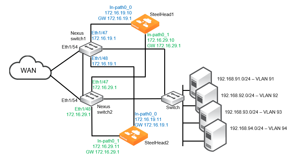
The example design includes the following:
• Each SteelHead is connected to both Nexus switches. In each case, the wan0_0 interface is directly attached to the Nexus switch1 and the wan0_1 interface is attached to Nexus switch2.
• If desired, the SteelHeads can be configured with data store sync.
• If a single SteelHead in-path interface fails, or the corresponding Nexus switch port fails, all traffic is redirected to the remaining three SteelHead interfaces.
• If a single SteelHead fails, all traffic is redirected to both in-path interfaces on the remaining SteelHead.
• The Nexus switches are running a minimum of NX-OS release 7.0(3)I7(6).
• The ITD device group contains four nodes, with each node being a different SteelHead in-path interface.
• The SteelHead Primary interfaces are not shown.
• Additional networking equipment (such as router, firewall, and so on) that may exist between the Nexus switches and WAN is not shown.
SteelHead configuration
The configuration of SteelHead1 and SteelHead2 for the example shown above is a standard virtual in-path deployment scenario with multiple in-path interfaces. It also includes Connection Forwarding and datastore sync to the second SteelHead. The following commands provide the basic settings for SteelHead1:
steelhead1 > enable
steelhead1 # configure terminal
steelhead1 (config) # interface inpath0_0 ip address 172.16.19.10 /24
steelhead1 (config) # ip in-path-gateway inpath0_0 172.16.19.1
steelhead1 (config) # interface inpath0_1 ip address 172.16.29.10 /24
steelhead1 (config) # ip in-path-gateway inpath0_0 172.16.29.1
steelhead1 (config) # in-path enable
steelhead1 (config) # in-path interface inpath0_1 enable
steelhead1 (config) # steelhead communication multi-interface enable
steelhead1 (config) # steelhead communication enable
steelhead1 (config) # steelhead name steelhead2 main-ip 172.16.19.11
steelhead1 (config) # steelhead name steelhead2 additional-ip 172.16.29.11
steelhead1 (config) # steelhead communication allow-failure
steelhead1 (config) # steelhead communication advertiseresync
steelhead1 (config) # in-path simplified routing "none"
steelhead1 (config) # in-path oop enable
steelhead1 (config) # datastore sync master
steelhead1 (config) # datastore sync peer-ip <IP_address_of_steelhead2_primary_interface>
steelhead1 (config) # datastore sync enable
steelhead1 (config) # write memory
steelhead1 (config) # restart
The settings for SteelHead2 are similar:
steelhead2 > enable
steelhead2 # configure terminal
steelhead2 (config) # interface inpath0_0 ip address 172.16.19.11 /24
steelhead2 (config) # ip in-path-gateway inpath0_0 172.16.19.1
steelhead2 (config) # interface inpath0_1 ip address 172.16.29.11 /24
steelhead2 (config) # ip in-path-gateway inpath0_0 172.16.29.1
steelhead2 (config) # in-path enable
steelhead2 (config) # in-path interface inpath0_1 enable
steelhead2 (config) # steelhead communication multi-interface enable
steelhead2 (config) # steelhead communication enable
steelhead2 (config) # steelhead name steelhead1 main-ip 172.16.19.10
steelhead2 (config) # steelhead name steelhead1 additional-ip 172.16.29.10
steelhead2 (config) # steelhead communication allow-failure
steelhead2 (config) # steelhead communication advertiseresync
steelhead2 (config) # in-path simplified routing "none"
steelhead2 (config) # in-path oop enable
steelhead2 (config) # no datastore sync master
steelhead2 (config) # datastore sync peer-ip <IP_address_of_steelhead1_primary_interface>
steelhead2 (config) # datastore sync enable
steelhead2 (config) # write memory
steelhead2 (config) # restart
Nexus configuration
Using the design illustrated above, the following commands can be used to enable and configure ITD on the Nexus switch1:
switch1(config)# feature itd
switch1(config)# itd device-group RB-DC
switch1(config-device-group)# node ip 172.16.19.10
switch1(config-device-group)# node ip 172.16.19.11
switch1(config-device-group)# node ip 172.16.29.10
switch1(config-device-group)# node ip 172.16.29.11
switch1(config-device-group)# probe icmp
As described in
ITD device groups, the
probe icmp command can be replaced with
probe tcp port 7800.
switch1(config)# itd branch-to-dc
switch1(config-itd)# device-group RB-DC
switch1(config-itd)# ingress interface Eth1/54
switch1(config-itd)# load-balance method src ip buckets 128
switch1(config-itd)# access-list branch-to-dc
switch1(config-itd)# no shut
switch1(config)# itd dc-to-branch
switch1(config-itd)# device-group RB-DC
switch1(config-itd)# ingress interface Vlan91
switch1(config-itd)# ingress interface Vlan92
switch1(config-itd)# ingress interface Vlan93
switch1(config-itd)# ingress interface Vlan94
switch1(config-itd)# load-balance method dst ip buckets 128
switch1(config-itd)# access-list dc-to-branch
switch1(config-itd)# no shut
switch1(config)# ip access-list branch-to-dc
switch1(config-acl)# 10 permit tcp <client-subnets> 192.168.0.0/16
switch1(config-acl)# exit
switch1(config)# ip access-list dc-to-branch
switch1(config-acl)# 10 permit tcp 192.168.0.0/16 <client-subnets>
switch1(config-acl)# exit
The configuration settings for the Nexus switch2 are identical:
switch2(config)# feature itd
switch2(config)# itd device-group RB-DC
switch2(config-device-group)# node ip 172.16.19.10
switch2(config-device-group)# node ip 172.16.19.11
switch2(config-device-group)# node ip 172.16.29.10
switch2(config-device-group)# node ip 172.16.29.11
switch2(config-device-group)# probe icmp
As described in
ITD device groups, the
probe icmp command can be replaced with
probe tcp port 7800.
switch2(config)# itd branch-to-dc
switch2(config-itd)# device-group RB-DC
switch2(config-itd)# ingress interface Eth1/54
switch2(config-itd)# load-balance method src ip buckets 128
switch2(config-itd)# access-list branch-to-dc
switch2(config-itd)# no shut
switch2(config)# itd dc-to-branch
switch2(config-itd)# device-group RB-DC
switch2(config-itd)# ingress interface Vlan91
switch2(config-itd)# ingress interface Vlan92
switch2(config-itd)# ingress interface Vlan93
switch2(config-itd)# ingress interface Vlan94
switch2(config-itd)# load-balance method dst ip buckets 128
switch2(config-itd)# access-list dc-to-branch
switch2(config-itd)# no shut
switch2(config)# ip access-list branch-to-dc
switch2(config-acl)# 10 permit tcp <client-subnets> 192.168.0.0/16
switch2(config-acl)# exit
switch2(config)# ip access-list dc-to-branch
switch2(config-acl)# 10 permit tcp 192.168.0.0/16 <client-subnets>
switch2(config-acl)# exit
For more details on the Nexus commands and syntax, consult the relevant documentation for your model of Nexus switch.
Additional design and configuration settings
This section describes additional design and configuration settings.
Correct Addressing and Transparency modes
By default, SteelHead peers will use Correct Addressing on the Inner Channel between themselves when optimizing traffic. But you can also use Port Transparency or Full Transparency for some or all optimized traffic flows. In either case, no additional specific ITD related configuration settings are required on the SteelHead or on the Nexus switch to support this type of scenario.
IPv4 and IPv6 deployments
SteelHeads are able to provide optimization for traffic where IPv6 is the addressing scheme in the network infrastructure.
However, not all Nexus switch models support IPv6. Therefore, consult the relevant Nexus documentation to confirm IPv6 support.
Even if your Nexus switch model does support IPv6, there are still some caveats related to ITD configuration. These may include the following:
• IPv6 does not support node level probes, only device group level probes are supported.
• IPv6 device group level probes support TCP, ICMP protocols but do not support HTTP, UDP, and DNS protocols.
Other caveats may also exist and should be confirmed by consulting the documentation for your Nexus switch model.
Flow data in ITD deployments
In virtual in-path deployments such as ITD, traffic moves in and out of the same WAN interface. The LAN interface is not used. When the SteelHead exports data to a data flow collector, all traffic has the WAN interface index. Although it is technically correct for all traffic to have the WAN interface index because the input and output interfaces are the same, it is impossible to use the interface index to distinguish between LAN-to-WAN and WAN-to-LAN traffic.
You can configure the fake index feature on your SteelHead to insert the correct interface index before exporting data to a data flow collector.
Verifying and troubleshooting ITD deployments
This section describes some of the basic commands and tools available for verifying and troubleshooting configurations.
To verify the ITD configuration
• On the Nexus switch, at the system prompt, enter the following commands:
enable
show running-config services
Look for the "feature ITD" content in the command output.
To verify the access control list configuration
• On the Nexus switch, at the system prompt, enter the following commands:
enable
show ip access-lists <ITD_service_name>
To verify the SteelHead configuration
• Connect to the Riverbed CLI on the ITD SteelHead and run show commands to view and confirm the relevant settings related to ITD deployments. For example:
show in-path
show interfaces configured