How a Packet Traverses a SteelConnect Network
This topic describes how the SteelConnect gateway processes packets as they traverse the network.
The SteelConnect gateway is configured and managed from SteelConnect Manager (SCM). The gateway provides several network services, such as routing services and firewall services, as packets cross the appliance.
Sample SteelConnect network
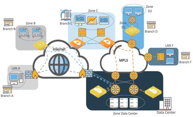
The topology in
Sample SteelConnect network uses these terms and definitions:
•A zone refers to a subnet that is local to the SD-WAN gateway or gateways at the site. A zone is configured on the LAN side of the gateway. The SteelConnect gateway can provide services to the clients such as DNS or DHCP; however, the default gateway or another device might perform these functions.
•In Branch D, Zone D1 is a local zone that is used to reach another zone (Zone D2) that is not directly connected to the gateway at Layer 3. This route is referred to as a third-party route in SCM.
The network paths shown in
Sample SteelConnect network use these conventions and definitions:
•Gray dotted lines illustrate a generic IPsec tunnel that has been created between a SteelConnect gateway appliance and a third-party firewall. This configuration is known as a Classic VPN in SteelConnect.
Note: With SteelConnect 2.11 or later, SteelHead SD appliances, the SDI-2030 gateway, and the SDI-5030 gateway do not support Classic VPN and cannot form IPsec tunnels with third-party devices (besides Zscaler).
•Blue dotted lines depict a RouteVPN tunnel. These VPN tunnels are automatically formed over the internet WAN between Riverbed SD-WAN appliances.
•Orange dotted lines represent the VPN tunnels built over a private WAN (for example, MPLS) when that WAN is configured in SCM to use encryption. You can enable encryption in SCM when you create a new WAN or edit an existing WAN in the Network Design section of the SCM user interface. In SCM, this configuration is called AutoVPN.
Orange and blue lines are collectively referred to as the overlay network. This term is an abstraction of the internet and WAN in which the gateways communicate with each other. The communication for the overlay network takes place on an underlay network. The underlay is the series of network devices owned by a provider or customer making up a network infrastructure.
SteelConnect gateway services
The SteelConnect gateway uses these services:
Routing services overview
SteelConnect gateways provide these routing services:
•Path selection - SCM uses traffic path rules to provide path selection. The path is selected by the gateway where the traffic originates and reflected by the gateway on the remote end. For example, traffic from Zone C to the Data Center can be configured to prefer the internet path over the private WAN. These rules have automation built in to select the better path based on quality metrics. Latency, loss, and jitter are also used in the calculation, if configured.
You can also define traffic path rules to force some traffic to use the underlay as opposed to be transported through the overlay between two Riverbed SD-WAN gateways.
•Quality of Service - The gateway ensures efficient use of bandwidth and leverages the common applications kept enhanced (CAKE) scheduling mechanism. CAKE uses an advanced fair queue mechanism based on hierarchical priority that distributes bandwidth while considering packet delays. CAKE is a connection-based system that tracks latency on each connection or traffic flow rather than bandwidth per class. CAKE is purposely built for internet-based uplinks so it is ideal for dynamic WAN throughput.
You can configure QoS in the outbound and inbound directions on the uplinks only. Branch gateways support both marking and enforcement.
The SDI-5030 gateway does not support QoS enforcement because it is out-of-path and your QoS enforcement endpoint should be on your existing MPLS routers.
Traffic forwarding mechanism
SteelConnect gateways provide the fundamental subset of router functionality of an edge router but do not have one-to-one parity with a traditional router.
SteelConnect gateways classify different network types by maintaining separate routing tables using these criteria:
Local - The LAN subnets managed by the SteelConnect gateway. In
Sample SteelConnect network, Zones B, C, and D1 are subnets considered as local for their respective appliance.
Overlay WAN - Subnets that are created as zones on SCM and advertised as reachable on the overlay network. The appliance in site B is aware of remote zones C, D1, D2, and the data center using the overlay WAN.
Underlay WAN - Any WAN forwarding decisions that are made outside of (or “under”) the SteelConnect overlay. For underlay connectivity on the WAN, the site must either participate in underlay learning with dynamic routing or configure the transfer network for the WAN. (See the
SteelConnect Manager User Guide for details.) In the example in
Sample SteelConnect network, Branch C would discover LAN F through routing protocols such as BGP or OSPF. The LAN F subnet appears in the underlay routing table of the gateway.
Classic VPN - Creates a manual VPN tunnel using the standard IPsec IKEv1 or IKEv2 protocol. A remote gateway is not necessary. For example, the tunnel could be terminated by a firewall or router or another networking device. LAN A’s subnet would appear in the Classic VPN table of Branch B’s gateway.
SteelHead SD appliances, the SDI-2030 gateway, and the SDI-5030 gateway don’t support ClassicVPN in SteelConnect version 2.11 and later. The data center firewall can terminate IPsec tunnels coming from legacy sites such as Branch A. Alternatively, a SteelConnect gateway such as SDI-1030 or virtual gateway could be deployed in the data center to terminate IPsec tunnels from legacy sites.
Statically defined routes - Typically, networks behind Layer 3 routers on the LAN side of the gateway. In SteelConnect terminology, this is called a third-party routing configuration. D2’s subnet appears as a third-party/static route in SteelConnect. However, on SteelHead SD appliances (and the SDI-2030 gateway), those routes are known as static routes.
Forwarding of traffic is done in two stages:
1. A route lookup is performed across all route tables. For a given destination address, the route lookup returns all available paths with the most specific prefix match.
2. The selection of the path is based on policies. You can configure a default path preference at the site or organization level. You can configure more specific traffic path rules to take precedence over less specific rules.
Overlay paths are always preferred over underlay paths when routes with equal prefixes match.
The following examples illustrate the forwarding logic.
In the examples, we assume that BGP is implemented as the routing protocol to exchange routes on the MPLS network.
Example 1: Branch B to Branch A
In this example, a host (10.1.2.15) in Branch B wants to connect to a server (10.1.1.250) in Branch A.
Branch B to Branch A routing example
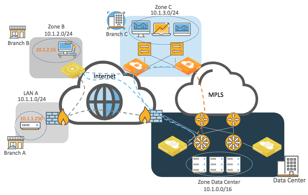
At the organization level, traffic uses this default path preference:
1. RouteVPN
2. MPLS
The SteelConnect gateway in Branch B has these entries in its routing table:
•Local: 10.1.2.0/24 directly connected
•Overlay WAN:
–10.1.3.0/24, Branch C zone is defined in SteelConnect Manager.
–10.1.0.0/16, Data Center zone defined in SteelConnect Manager.
•Underlay WAN: Not used because the two sites do not have a common network. If the overlay fails and because we are using classless addressing, there is not a way to route traffic over the internet.
•Classic VPN: 10.1.1.0/24 learned from the IPsec tunnel to the firewall in Branch A
•Third-party zones/statically defined routes: Not used
The SteelConnect gateway in Branch B checks the routing table and chooses the most specific prefix match, which is the Classic VPN connection.
Example 2: Branch C to Branch F
In this example, a host (10.1.3.20) in Branch C wants to connect to a server (10.1.18.250) in Branch F.
Branch C to Branch F routing example
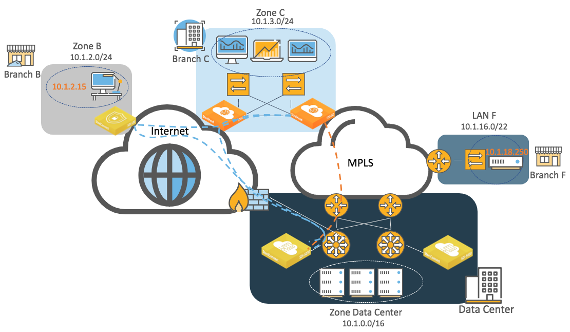
At the organization level, traffic uses this default path preference:
1. RouteVPN
2. MPLS
The SteelConnect gateway in Branch C has these entries in its routing table:
•Local: 10.1.3.0/24 directly connected
•Overlay WAN:
–10.1.2.0/24, Branch B zone defined in SteelConnect Manager
–10.1.0.0/16, Data Center zone defined in SteelConnect Manager
•Underlay WAN: Branch F MPLS CE router is advertising 10.1.16.0/22 on MPLS through BGP and the gateway in Branch C learns it through BGP.
•Classic VPN: Not used
•Third-party zones/statically defined routes: Not used
The SteelHead SD appliance in Branch C checks the routing table and chooses the most specific prefix match, which is the underlay network to MPLS.
Example 3: Branch B to Branch F
This example is similar to the previous one; however, in this scenario a host (10.1.2.15) in Branch B wants to connect to a server (10.1.18.250) in Branch F.
Branch C to Branch F routing example
Because Branch B is an internet-only site and Branch F is MPLS only, there is no common network to communicate. To communicate with a legacy site such as Branch F, you need to configure a transit site: you enable the transit feature and define the data center as a transit site. The data center appliances will redistribute the routes learned from the underlay (MPLS) and to the internet overlay (RouteVPN) and vice versa. Once configured, the SteelConnect gateway in Branch B will know that to reach LAN F, it must send traffic to the data center through the overlay network. Conversely, the Branch F legacy router will learn the Branch B subnet through BGP as the data center appliances will announce it on the underlay network (MPLS).
Example 4: Branch C to Branch D
In this example, a host (10.1.3.20) in Branch C wants to connect to a server (10.1.5.120) in Branch D.
Branch C to Branch D routing example
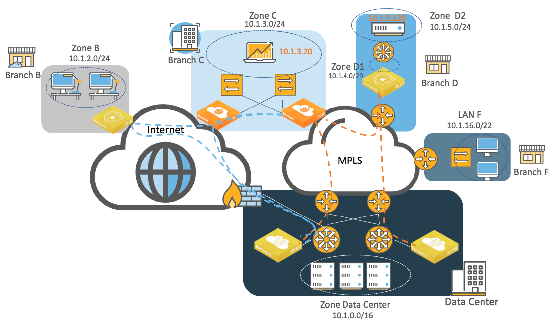
At the organization level, SteelConnect has been changed from the default and uses this path preference:
1. MPLS
2. RouteVPN
The SteelConnect gateway in Branch C has these entries in its routing table:
•Local: 10.1.3.0/24 directly connected
•Overlay WAN:
–10.1.2.0/24, Branch B zone defined in SteelConnect Manager
–10.1.0.0/16, Data Center zone defined in SteelConnect Manager
–10.1.4.0/29 and 10.1.5.0/24, Branch D zones defined in SteelConnect Manager
•Underlay WAN:
–10.1.16.0/22 learned from MPLS CE router in Branch F and learned from BGP
–10.1.4.0/29 and 10.1.5.0/24 that Branch D gateway advertises through BGP
•Classic VPN: Not used
•Statically defined routes: Not used
The route lookup finds two available paths for 10.1.5.120. The SteelConnect gateway in Branch D is advertising its local and third-party subnets on the overlay but it is also advertising on the underlay using BGP or OSPF.
Because overlay paths are always preferred over the underlay path for equal prefix, the traffic will be routed on the AutoVPN tunnel between Branch C and Branch D.
If a host in Branch B wants to communicate with a server in Branch D while they are in different WANs, it is possible to establish the communication between the two using the alternate hub feature.
Packet operation flow
When a packet is processed by a SteelConnect gateway, the logical order of the operation flow is from left to right as shown in
Packet operation flow. Connection tracking, highlighted in yellow, maintains the state for packets of a flow.
Packet operation flow
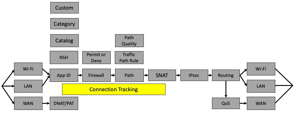
Packets arrive to the gateway on a Wi-Fi, LAN, or Ethernet interface. These interfaces differ slightly in terms of how traffic is handled. LAN interfaces on some gateway hardware have a switch inside and traffic between interfaces in the same zone on a LAN interface will be switched at Layer 2, bypassing the features described.
After traffic arrives, SteelConnect classifies it based on the application and tracks this classification for all packets in a flow. The firewall is invoked and will act on packet headers or, if needed, wait until the application is identified. Following the firewall, SteelConnect might select a path for the overlay based on a traffic path rule and quality. After it selects the path, it performs any source NAT and the packet might be encrypted. Following the encryption process, the packet is handed over to an interface and the per-interface routing table is consulted. In the case of packets going out a WAN interface (uplink), the packet might have QoS applied.
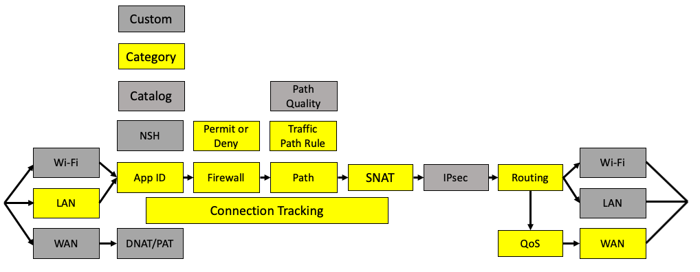
The following examples show additional details of how a packet is processed by the SteelConnect gateway as it traverses an SD-WAN network. Keep in mind that SteelConnect can skip some steps in the left-to-right flow. In these examples, the functions that are in use are highlighted in yellow and the functions that are skipped are in gray.
Example: Traffic sent from site to site
In this topology, traffic is sent from one site to another over the WAN.
Traffic sent from site to site shows how packets are processed at the originating SteelConnect appliance (source) before the traffic is sent over the WAN to the remote gateway.
Traffic sent from site to site

Packets are processed in this order:
1. Traffic arrives on an interface, is not malformed, and passes header validation checks.
2. Application ID is checked and the application catalog is used.
3. Connection tracking maintains the state for packets of a flow.
4. The firewall determines that traffic from the local zone to the remote zone for this application is permitted.
5. Path selection can use the organizational default when a zone is a member of more than one WAN but, in this case, a traffic path rule is used to steer the application. In SCM terms, an organization is a company representing an end customer. The traffic path rule has path quality override configured and the path decision is overridden due to quality (latency, loss, and/or jitter).
6. Traffic is encrypted using Encapsulating Security Payload (ESP) protocol and encapsulated in a UDP header with a destination for the remote gateway uplink IP address connecting to the WAN that has the better quality metrics.
7. Routing determines the next hop out the uplink interface.
8. QoS scheduling is performed to minimize delay.
9. Traffic is sent out the WAN interface.
This flow also includes traffic to zones not directly connected to the gateway at Layer 3, referred to as a third-party route.
Example: Traffic to the internet
In this topology, traffic is destined outbound to the internet.
Traffic outbound to the internet
Packets are processed in this order:
1. Traffic arrives on a LAN interface, is not malformed, and passes header validation checks.
2. Application ID is learned from the catalog and belongs to a category that is used for determination in the rules.
3. Connection tracking maintains the state for packets of a flow.
4. The firewall determines that traffic from the local zone to the internet for this application is permitted.
5. Path selection uses a traffic path rule to send this application directly to the internet overriding the organizational default for internet egress.
6. Source IP should have network address translation.
7. Routing determines that the destination is to the internet.
8. QoS performs scheduling is performed to minimize delay.
9. Traffic is sent out the WAN interface (uplink).
Example: Inbound traffic
This topology shows how a packet is processed by the SteelConnect gateway when it arrives from the WAN. This topology is for all traffic destined to a server in the local network on the site arriving from the internet. A common use case is an inbound connection to the web server hosted at a site.
Traffic arriving inbound from the WAN

Packets are processed in this order:
1. Traffic arrives on the WAN interface for a destination IP address of the uplink and the MAC address of the uplink. The packet passes header validation checks.
2. Destination NAT is performed for traffic to reach the internal device.
3. The application ID is a custom application created for any traffic to the destination that is a defined device. In SCM, any inbound traffic has to be defined to a device using a custom application unless the WAN is configured as trusted.
4. Connection tracking maintains the state for packets of a flow.
5. The firewall determines that traffic from the internet to a device in a local zone is permitted and that the destination IP should have NAT to the private IP address.
6. Routing determines the destination to the local device.
Packet operation flow on SteelHead SD appliances and the SDI-2030 gateway
The software architecture on SteelHead SD appliances and the SDI-2030 gateway is very different from SteelConnect SDI-130, SDI-330, SDI-1030, and SDI-vGW gateways as of version 2.11 or later. As such, the packet operation flow is slightly different but follows the same logic.
Packet flow for SteelHead SD appliances and the SDI-2030 gateway
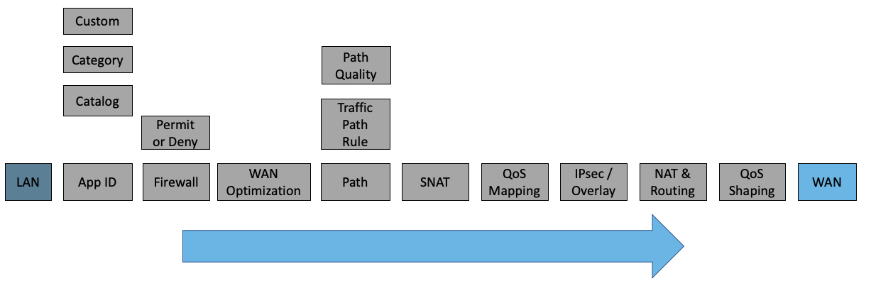
The SDI-2030 gateway does not offer WAN optimization services.