Branch Topologies for SDI
This topic describes the primary validated designs for branch deployments with SteelConnect SD-WAN gateways SDI-130, SDI-130W, SDI-330, SDI-1030, and SDI-vGW. The topologies are grouped by their network position.
The SDI-2030 and SDI-5030 gateways operate in different ways than the rest of the SDI gateways. Although you can deploy the SDI-2030 gateway in branches, they share the software architecture and routing stack with SteelHead SD. The SDI-5030 gateway is positioned out-of-path in the data center and is described in
Data Center Topologies. LAN topologies for SDI branches
This section explains how to configure the LAN side of the SteelConnect gateway. It includes these possible deployment scenarios for SDI gateways:
This list of possible scenarios highlights some of the most common deployments, but it is not an exhaustive list.
To learn more about how to create and configure sites and VLANS (zones) for your topology, see the SteelConnect Manager User Guide.
Spanning tree on LAN ports
Spanning Tree Protocol (STP) is a Layer 2 protocol that passes data back and forth to find out how the switches and gateways are organized on the network and uses this information to create a logical spanning tree. Each site configures a different spanning tree.
STP is active by default on the SteelConnect gateway LAN ports and it prevents network malfunction by blocking ports that cause loops in redundant network paths.
The SDI-1030 gateway and SDI-vGW on ESX do not support Spanning Tree.
STP is disabled on branch gateways configured for high availability. Due to the lack of STP, we recommend attaching only one switch to one gateway and avoiding mesh topologies with HA deployments.
The original version of Spanning Tree IEEE 802.1D takes between 30 to 50 seconds to converge in a network. Rapid Spanning Tree Protocol (RSTP) defined in 802.1w is an enhanced version with convergence time of 6 seconds (3x2 hello interval or even lower).
SteelConnect gateways and switches implement Multiple Spanning Tree (MST) protocol defined in IEEE 802.1s. MST uses the best features of PVST+ and RSTP, and MST can run a single instance of Spanning Tree Protocol for a group of VLANs. In a network of 1000 VLANs, you can group the first 500 VLANs into MST group 1 and the last 500 VLANs into MST group 2, which reduces 1000 VLAN instances in RPVST+ to just two logical instances.
All spanning tree operations include these four primary steps:
1. Determining a root bridge.
2. Selecting a root port.
3. Selecting designated ports.
4. Blocking ports with loops.
The election of a root bridge is the most crucial step and dictates the movement of Layer 2 traffic. A device with the lowest bridge priority becomes a root bridge in the network. If there is a tie with bridge priority, then the device with the lowest MAC address becomes the root bridge. Unlike other vendors, we do not employ default bridge priority of 32768 because SteelConnect access points have the lowest MAC addresses of all Riverbed products.
All SteelConnect devices start with MAC address 6C:98:EB.
The following are the default priorities:
•SDI-S48 - 12288
•SDI-S24 - 16384
•SDI-S12 - 20480
•SDI-330 - 24576
•SDI-130 - 28672
•SDI-AP5/5r - 36864
•SDI-AP3 - 40960
Although access points currently have higher priority, do not change the value or decrease the default priority, which would result in access points becoming a root bridge in your network.
For example, if you have a combination of S48 and S24 switches and a gateway, then the S48 switch will assume the role of root bridge.
When SteelConnect appliances are deployed in a multivendor environment where a root bridge is already elected, we recommend using Root Guard, BPDU Guard, or Loop Guard features or reducing the existing root bridge priority to less than 12288 to avoid or reduce downtime.
Layer 2: Access port
This deployment features switches with access port connections configured in a single zone.
This topology can have a SteelConnect gateway acting as a switch, a single switch, or a pair of switches.
Layer 2 deployments with access port connection
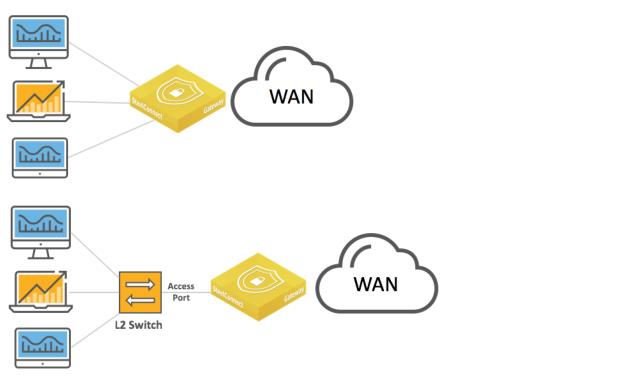
Layer 2 deployment with dual switches and access port connections
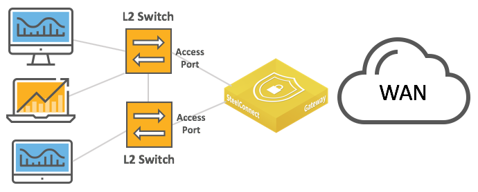
In these topologies, Spanning Tree is active by default on the SteelConnect gateway LAN ports and prevents network malfunction by blocking ports that cause loops.
In this topology, you configure the switch uplink port as an access port.
The following SteelConnect gateways support this topology.
SDI-VGW | SDI-130/130W | SDI-330 | SDI-1030 |
| | | |
You can deploy the SteelConnect virtual gateway (SDI-VGW) on a universal customer premises equipment (uCPE) or a Riverbed SteelFusion appliance. As long as physical ports are attached to the ports of the virtual appliance, the gateway will support similar topologies.
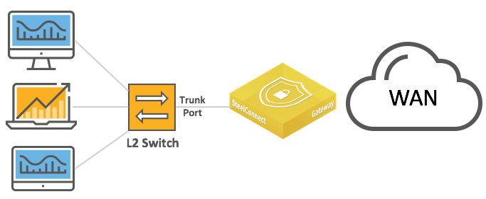
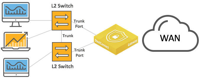
Layer 2: Trunk port
This deployment features switches with trunk port connections for multizone environments.
Layer 2 deployments with trunk port
Layer 2 deployments with trunk port and dual switches
The following SteelConnect gateways support this topology.
SDI-VGW | SDI-130/130W | SDI-330 | SDI-1030 |
| | | |
As of SteelConnect 2.11 or later, native VLAN is supported.
To configure the switch and SCM with trunk port
1. Physically connect the Layer 2 switch to a LAN port on the SteelConnect gateway.
2. Configure the connected port as a trunk/ 802.1q tagged port.
In SCM, choose Appliances > Ports, select a LAN port and select Multizone (VLAN tagged) from the drop-down Port mode list.
LAN port mode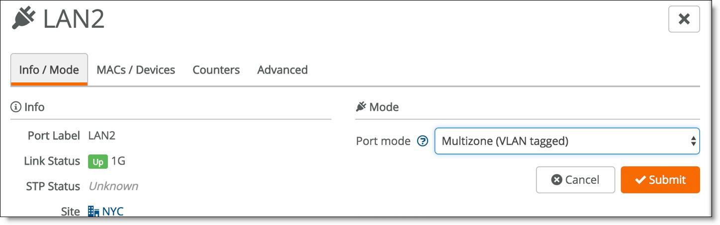
3. Configure the core switch with a trunk port to connect to the SteelConnect gateway.
Here is a sample configuration:
interface GigabitEthernet1/2
description ToSteelConnectGateway
switchport trunk encapsulation dot1q
switchport trunk allowed vlan all
switchport mode trunk
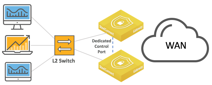
Layer 2: High availability
High availability on the LAN provides network redundancy and reliability and maintains uninterrupted service in the event of a power, hardware, software, or WAN uplink failure. Gateways in an HA pair must be the same models.
LAN high-availability topology and
LAN high-availability topology with dual switches show the supported configurations.
LAN high-availability topology
LAN high-availability topology with dual switches
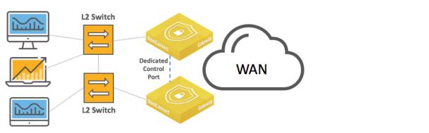
The interconnections between the SteelConnect HA pair and the Layer 2 switch can be configured as access mode (singlezone) or trunk/802.1q (multizone).
The Spanning Tree Protocol (STP) is disabled on branch gateways configured for high availability. Without STP, we recommend you attach only one switch to a gateway and avoid mesh topologies.
The HA pair uses the Dedicated Control Port to communicate with each other, and that port serves as the VRRP link between the two gateways.
To avoid traffic loops, do not use the dedicated control port to transmit data.
For SDI-1030 gateways, one port must be configured as the Dedicated Control Port by assigning the Control Port role.
Setting the Control Port
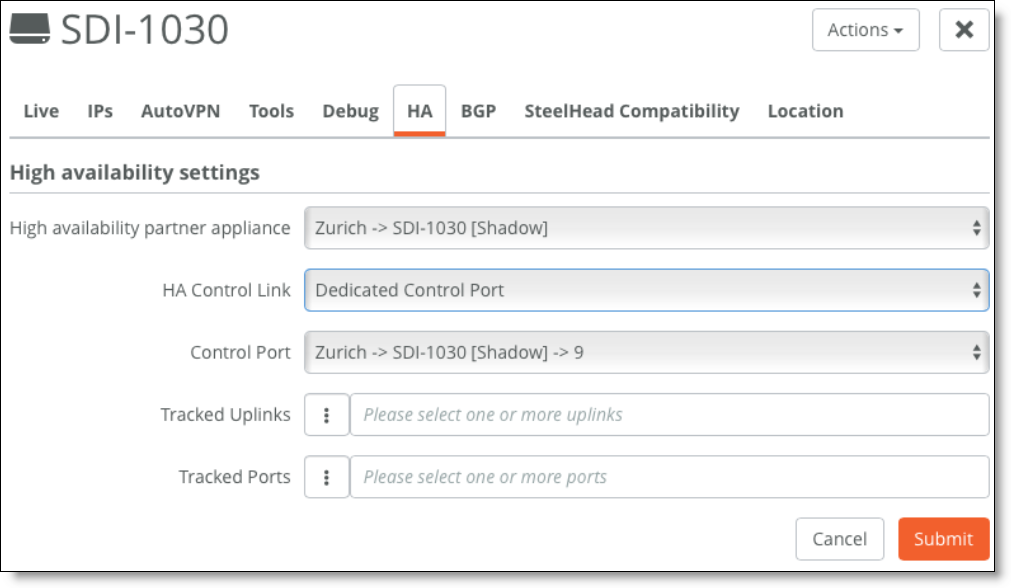
You can use tracked ports to trigger failover if the network goes down on the LAN side of the gateway (for example, if a switch fails) to avoid a black hole situation.
The following SteelConnect gateways support this topology.
SDI-VGW | SDI-130/130W | SDI-330 | SDI-1030 |
| | | |
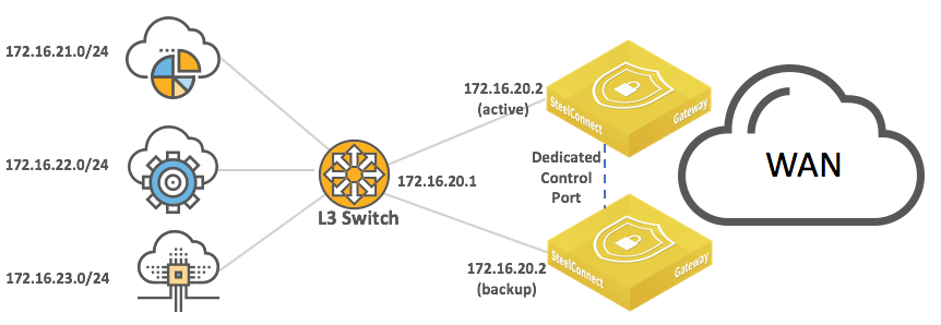
Layer 3: Switch behind a SteelConnect gateway with static routing
A typical use case for enterprise networks uses a core Layer 3 switch (or a pair of switches) handling inter-VLAN routing for the local network.
LAN topology with Layer 3 switch behind SteelConnect gateway with static routing
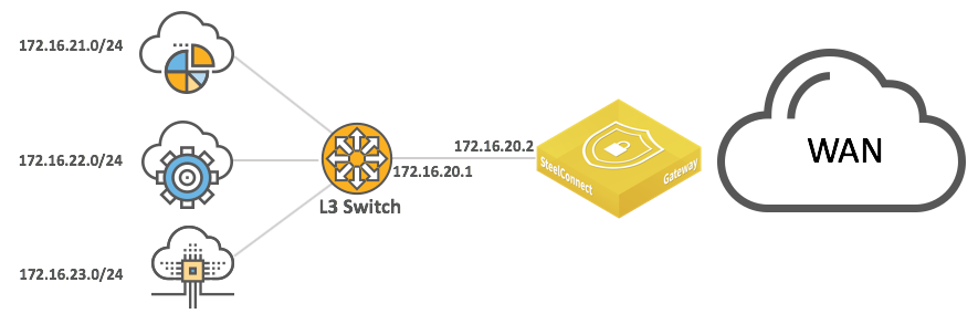
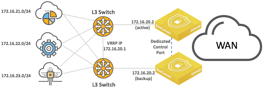
LAN topology with Layer 3 switch behind SteelConnect gateway with static routing
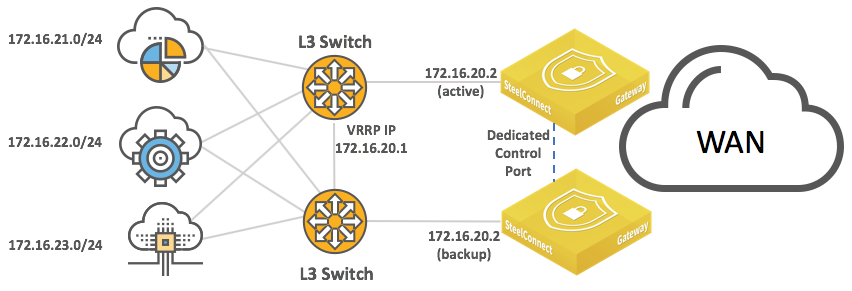
and high availability
Because SteelConnect appliances run high-availability in active/backup fashion, the backup appliance gets the LAN-facing IP address when the master appliance fails.
You can configure static routes:
•on the core switches to route traffic to the WAN through the SteelConnect gateway.
•on the SteelConnect gateway to identify the local subnets and be able to advertise them on the WAN.
The IP addresses and subnets are examples only. You can configure addresses appropriate for your network.
The following SteelConnect gateways support this topology.
SDI-VGW | SDI-130/130W | SDI-330 | SDI-1030 |
| | | |
To configure the switch and SCM to support a switch behind a gateway with static routing
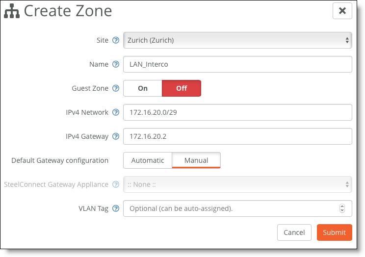
1. Create a zone for the LAN interconnection, or update the default LAN zone assigned to the site.
Creating a zone
2. Physically connect the Layer 3 switch to a LAN port on the SteelConnect gateway.
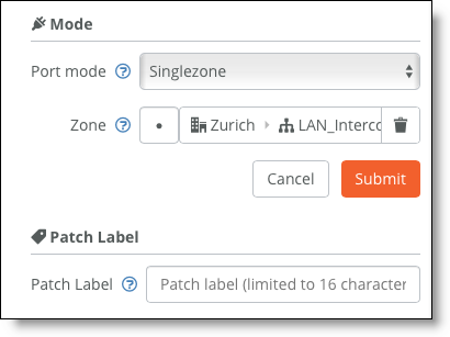
3. For the newly configured zone, configure the connected port under Port mode to be Singlezone.
Setting the port mode
4. Configure the switch port.
Here is a sample configuration:
Switch(config)# interface giga 0/1
Switch(config-if)# no switchport
Switch(config-if)# ip address 172.16.20.1 255.255.255.248
Switch(config-if)# no shutdown
Switch(config)# ip route 0.0.0.0 0.0.0.0 172.16.20.2
5. Test the connectivity between the two devices.
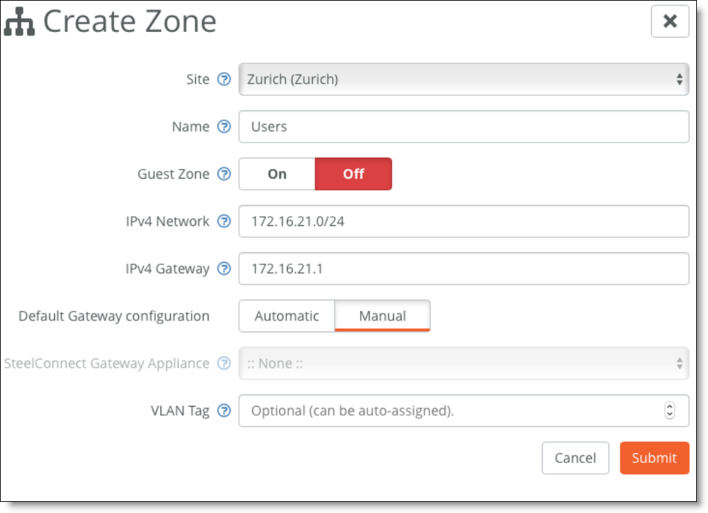
6. On SCM, for each local subnet, create a zone with a manual default gateway configuration.
Creating a zone with a manual default gateway configuration
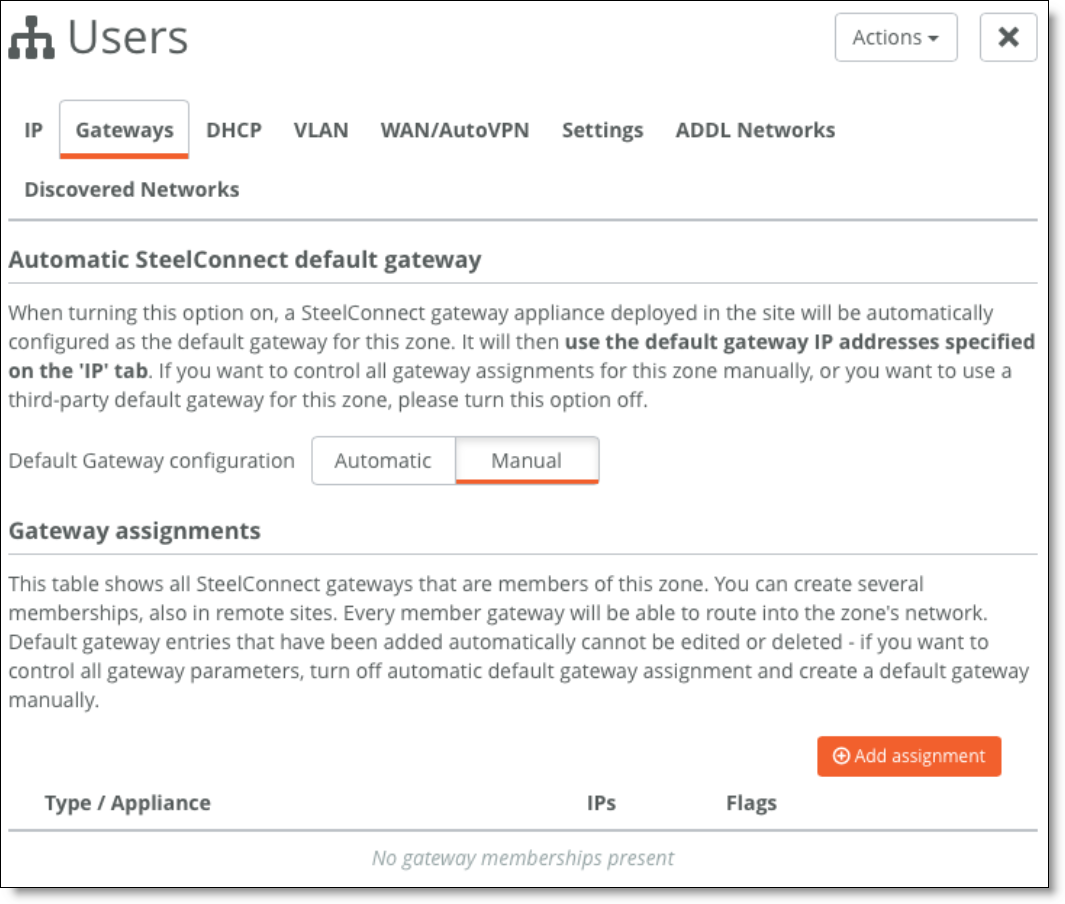
7. For the newly created zones, edit the configuration under the Gateways tab and delete the gateway assignment.
Deleting the gateway assignment
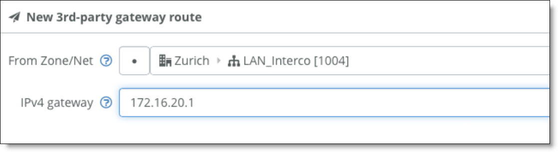
8. Select the Settings tab and create a third-party route for the gateway to reach the VLANs through the core switch.
3rd-party gateway route
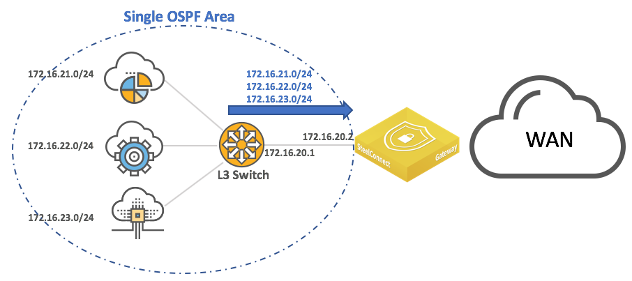
Layer 3: Switch behind a SteelConnect gateway with OSPF dynamic routing
An alternative to the previous configuration is to leverage dynamic routing protocols such as OSPF to discover subnets behind a Layer 3 switch.
LAN topology with Layer 3 switch behind SteelConnect gateway with dynamic routing
In this deployment, you must configure OSPF on the Layer 3 switch as well as on the SteelConnect Manager so that:
•the switch advertises the LAN subnets to the SteelConnect gateway.
•the SteelConnect gateway can learn the LAN subnets and eventually redistribute them on the WAN side as well as making SteelConnect Manager aware of those subnets in that site.
If you want the SteelConnect gateway to advertise a default route to the Layer 3 switch, BGP must be enabled. For more details, see
MPLS CE router replacement: ASBR-like deployment. However, the OSPF default-originate does not work when OSPF is enabled on the WAN side of the gateway, so we recommend you configure a default route on the L3 switch.
The following SteelConnect gateways support this topology.
SDI-VGW | SDI-130/130W | SDI-330 | SDI-1030 |
| | | |
To configure SCM to support a switch behind a gateway with OSPF dynamic routing
1. Create a zone for the LAN interconnection, or update the default LAN zone assigned to the site.
Creating a zone
2. Physically connect the Layer 3 switch to a LAN port on the SteelConnect gateway.
3. For the newly configured zone, set the connected port under Port mode to be Singlezone.
Setting the port mode
4. Configure the switch port accordingly.
Here is a sample configuration with OSPF:
Switch(config)# interface giga 0/1
Switch(config-if)# no switchport
Switch(config-if)# ip address 172.16.20.1 255.255.255.248
Switch(config-if)# no shutdown
Switch(config-if) router ospf 1
Switch(config-router)# network 172.16.20.1 0.0.0.0 area 0
Switch(config-router)# network 172.16.21.0 0.0.0.255 area 0
Switch(config-router)# network 172.16.22.0 0.0.0.255 area 0
Switch(config-router)# network 172.16.23.0 0.0.0.255 area 0
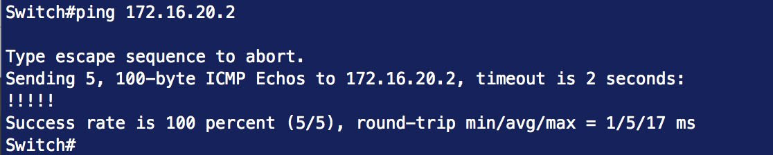
5. Test the connectivity between the two devices.
Testing connectivity
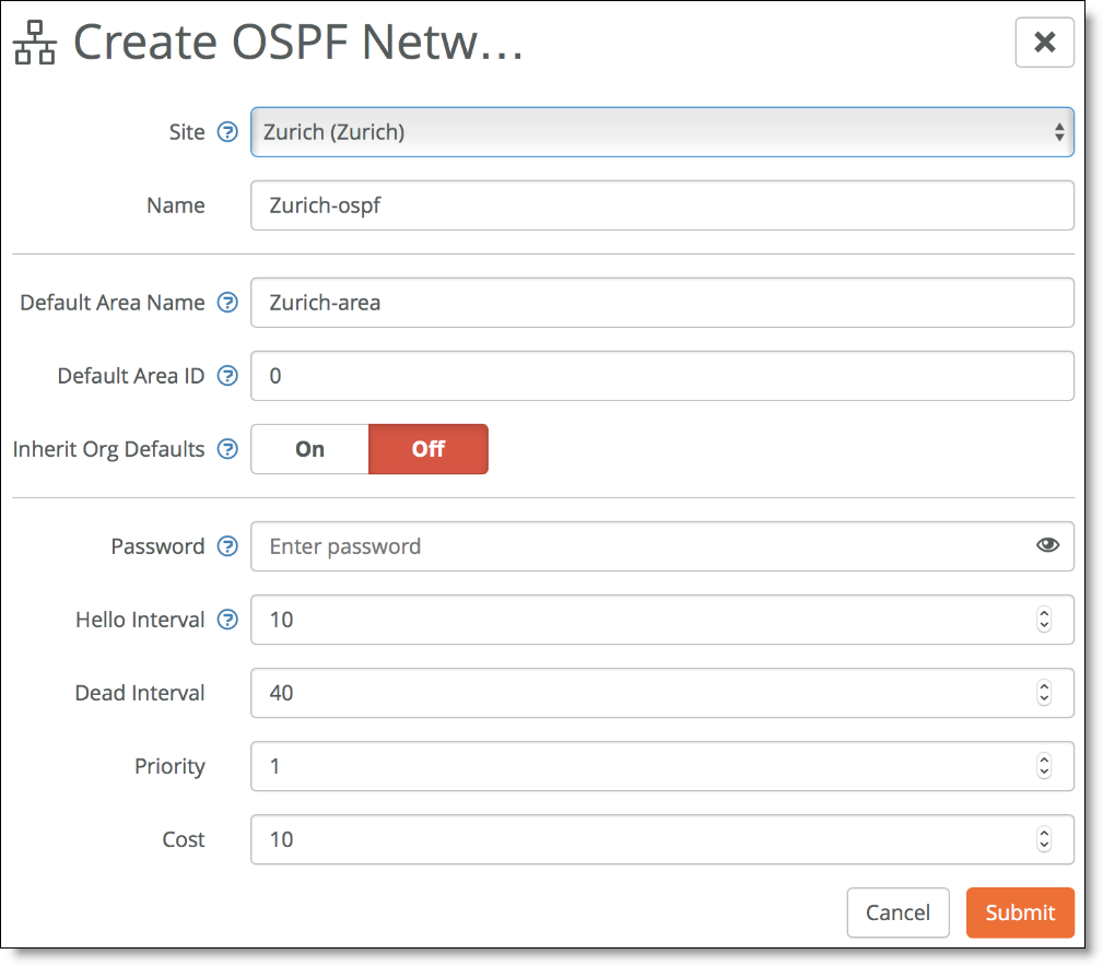
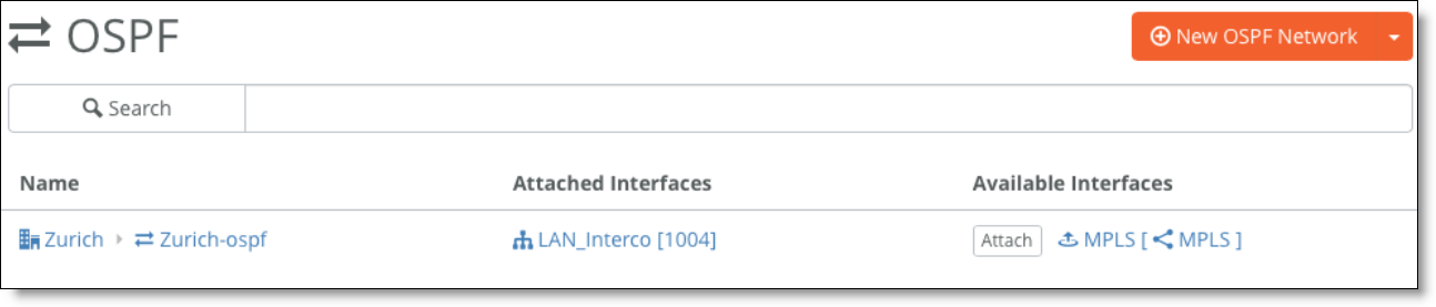
6. On SCM, choose Routing > OSPF and create a new OSPF network for the site.
Creating an OSPF network
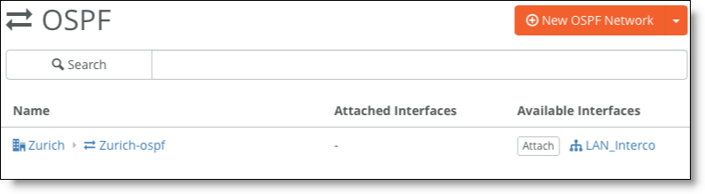
7. Attach the interface to learn the routes.
In this example, you attach the LAN_Interco interface.
Attach the interface to learn the routes
Attaching an OSPF interface
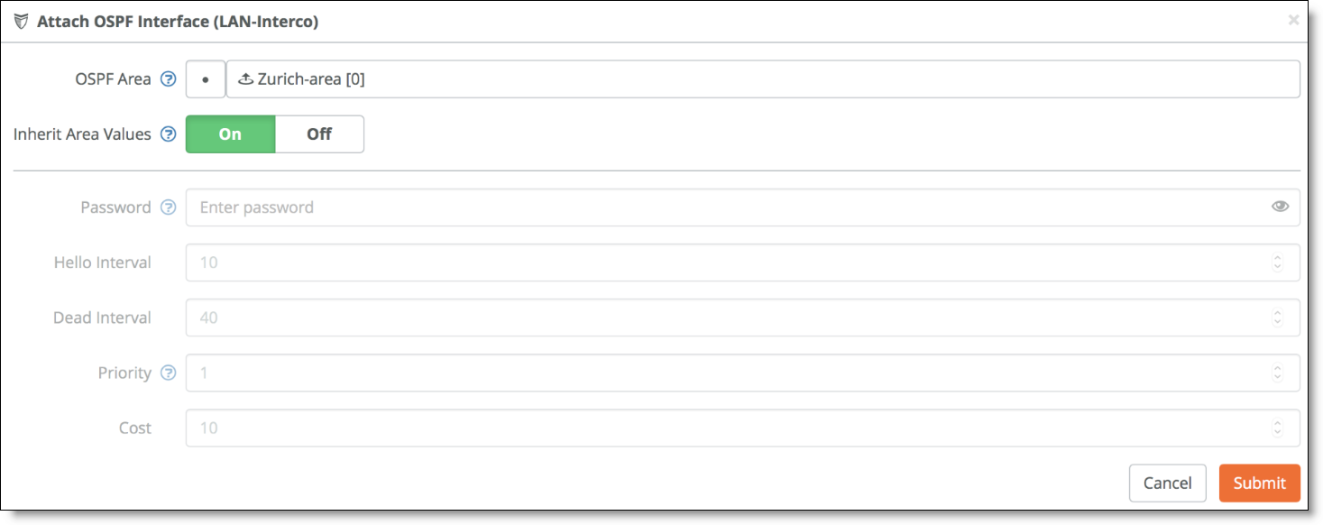
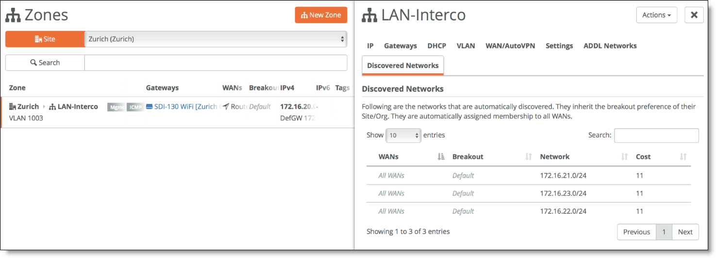
The SteelConnect gateway connects to its OSPF peer, in this case the Layer 3 switch on the LAN side, and starts discovering the LAN subnets. Discovered subnets are added to the LAN-Interco zone. You can view the discovered subnets in SCM by choosing Network Design > Zones, select the zone (such as LAN-Interco), and select the Discovered Networks tab.
Discovered networks
Layer 3: High availability
Configure the HA pair and the pair’s connection to the Layer 3 switch or router in the same way you would for a Layer 2 topology. See
Layer 2: High availability.
High-availability pair of gateways connected to a single Layer 3 switch or router
High-availability pair of gateways connected to two Layer 3 switches or routers
The following SteelConnect gateways support these topologies.
SDI-VGW | SDI-130/130W | SDI-330 | SDI-1030 |
| | | |
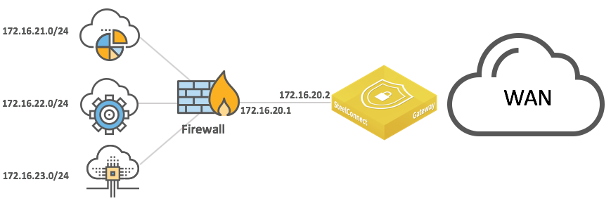
Integration with firewalls
LAN-side integration with firewalls is very similar to LAN topologies with Layer 3 switches. You can configure static routes or dynamic routing to reach subnets behind the firewalls.
LAN topologies with single firewall
LAN topologies with dual firewalls
HA LAN topologies with single firewall
HA LAN topologies with dual firewalls
If the firewall applies NAT-to-LAN traffic, the SteelConnect gateway only sees the firewall IP address, so there is no need to configure static routes or OSPF on the LAN side.
Double NAT can cause issues with some application traffic. You can configure gateway uplinks to skip outbound NAT to resolve double NAT issues.
Firewall clusters typically operate in active/passive mode. Each appliance has the same configuration, and if one goes down the other activates and resumes operation with the same IP addresses. The gateways do not detect a traffic loop.
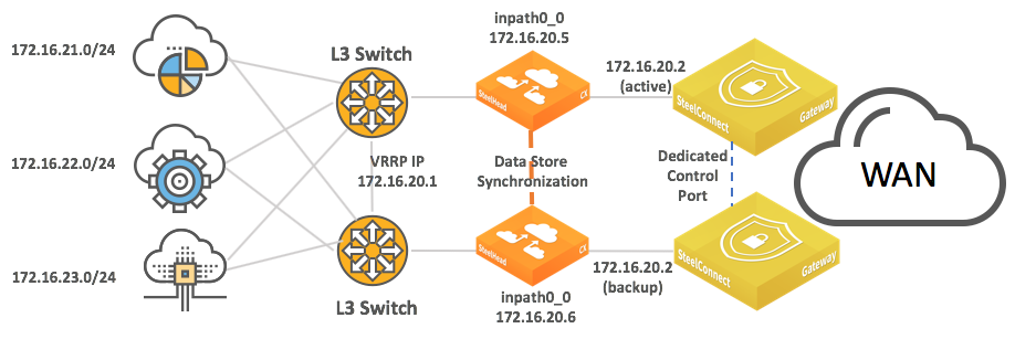
Integration with Riverbed SteelHead
You can deploy SteelConnect gateways with SteelHeads for WAN optimization.
SteelHead topology with HA gateways
SteelHead topology with HA gateway and dual switches
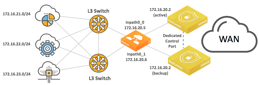
SteelHead topology with redundancy
By default, SteelConnect appliances have the SteelHead compatibility feature on.
To enable SteelConnect compatibility on a SteelHead CX, enter this Riverbed command-line interface (CLI) command: steelhead steel-connect compatibility enable
See the SteelConnect Manager User Guide for more information about compatibility.
See the SteelHead Deployment Guide and SteelHead User Guide for more details about the SteelHead appliance configuration and the various deployment options (including integration with firewalls).
WAN topologies for SDI branches
This section details common configurations of the WAN side of the gateway. It includes the following scenarios:
This list of possible scenarios highlights some of the most common deployments, but it is not an exhaustive list.
We recommend reading
SteelConnect and Network Security before reading this section.
Important configuration information for all WAN topologies
In all topologies, make sure that the LAN subnets (zones) are given the appropriate permissions. Each topology needs:
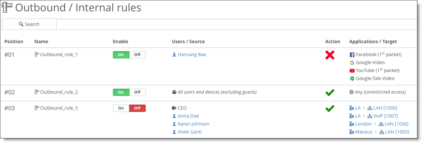
•Access resources on the internet as defined with the Outbound rules.
Defining access with outbound rules
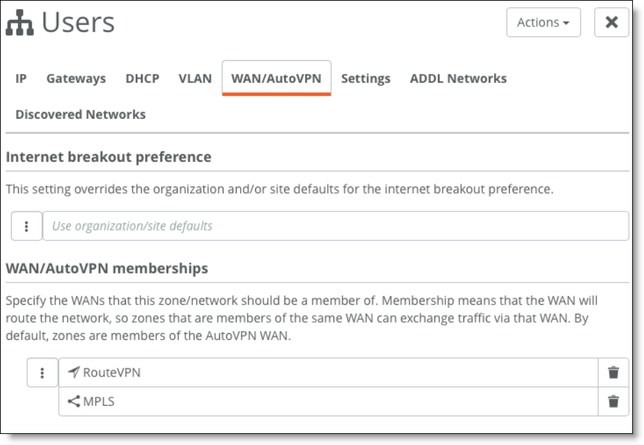
•Be advertised and send traffic on different WANs.
Check the WAN/AutoVPN membership in the Zone configuration.
Specify WAN/AutoVPN memberships
Single internet connection
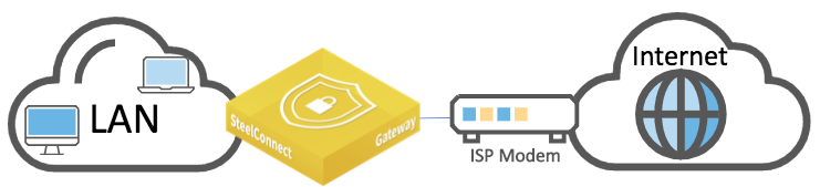
This internet-based WAN topology is a typical scenario for small to medium businesses that have a single broadband internet connection from their service provider.
SteelConnect gateway deployed physically on the LAN side of the customer premises equipment
The following SteelConnect gateways support this topology.
SDI-VGW | SDI-130/130W | SDI-330 | SDI-1030 |
| | | |
To configure an internet-based WAN topology
1. Connect the Ethernet LAN port of the internet modem to the WAN port of the SteelConnect gateway.
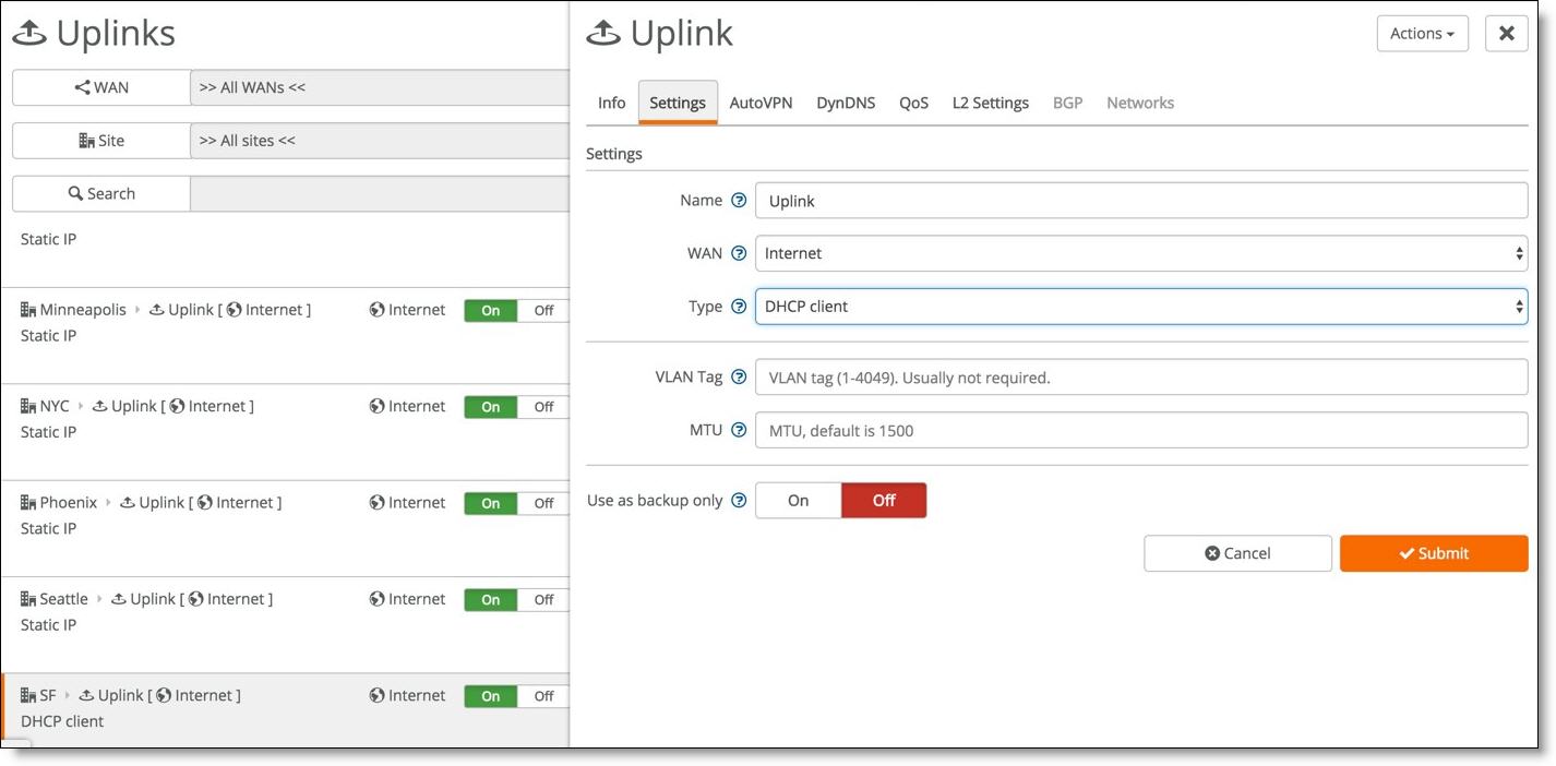
2. If the modem uses a DHCP address on its LAN interface, set the uplink for the gateway in the Type field on SCM to DHCP client.
Setting DHCP for the gateway uplink
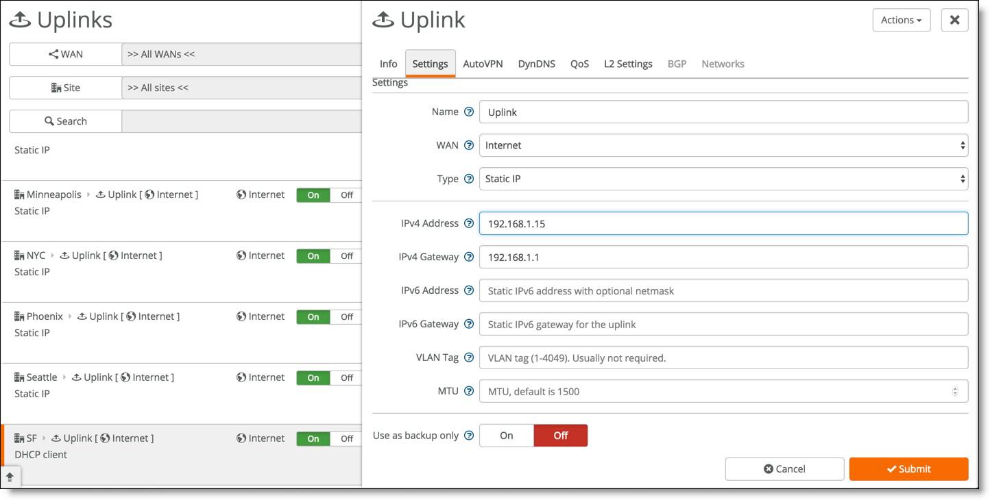
3. If the modem does not use DHCP, select Static IP and enter the IP address, address mask, and default gateway.
Setting static network details
To configure a static IP address on the uplink connection for the first time, you must configure the gateway using the USB method. By default, the gateway tries to get a DHCP IP address on its uplink interface and then communicates with the core services over the internet connection to determine its configuration. To set up a static IP address on an uplink, you can set up the configuration on SCM, even if the hardware is currently not present at the related site. You’ll need the serial number of the new gateway to create an offline provisioning configuration file.
To provision an appliance with a static IP address using the USB method:
–Select the uplink for the site and enter the IPv4 address as shown in Step 2.
–Register the appliance under Appliances > Add Appliances > Register Hardware Appliance. Enter the serial number of the SteelConnect gateway.
–Select the new hardware appliance, click Actions, and select Download config. The system downloads a configuration file named with the gateway serial number. Copy the file to a FAT32 formatted USB stick. The system does not support other file system types like Linux ext2,3,4, NTFS, and so on.
–Deploy the gateway on the site and power on the appliance. Wait at least 30 seconds until the new appliance powers up correctly before plugging in the USB stick. Plug in the USB stick to restore the configuration. Because the gateway does not mount the stick during boot up, it won’t import the configuration automatically. The gateway connects to SCM with the previously set up configuration.
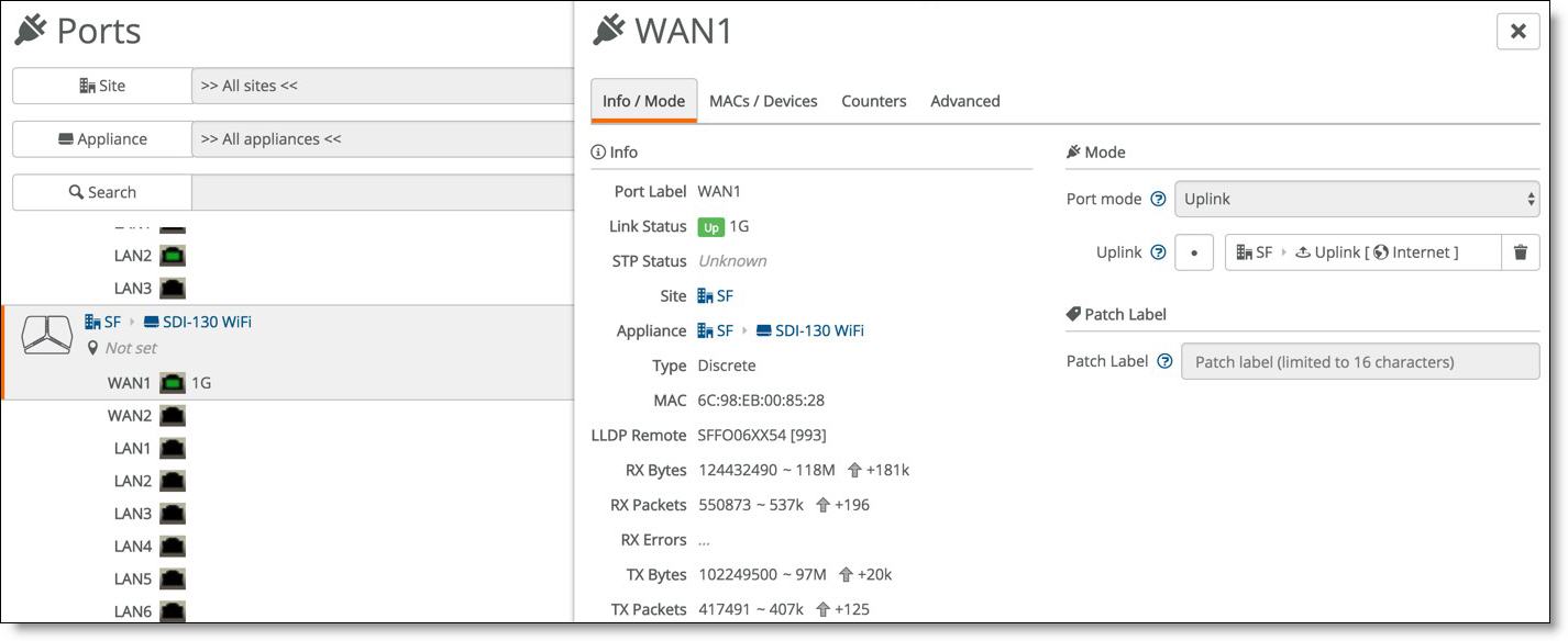
4. Ensure that the Port mode for the WAN port of the appliance at that site is set to Uplink.
Setting the port mode
In this topology, the gateway is NATed behind the cable modem. For SteelConnect to form an AutoVPN tunnel between two sites, at least one of the gateways must be reachable through a public IP address. When the SteelConnect gateways on both sites are behind a NAT gateway, you might need to configure port forwarding for UDP port 4500 on the modem/CPE. For more information about how to configure port forwarding for some commonly deployed modems/SOHO routers go to
https://portforward.com/router.htm.
Multiple internet connections
This internet-based WAN topology features multiple internet connections from different service providers.
Internet-based WAN topology
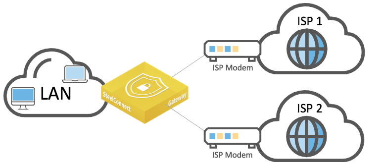
with multiple connections
The following SteelConnect gateways support this topology.
SDI-VGW | SDI-130/130W | SDI-330 | SDI-1030 |
| | | |
SDI-130 and SDI-330 have two uplink ports. You can configure SDI-VGW and SDI-1030 ports with up to seven uplinks.
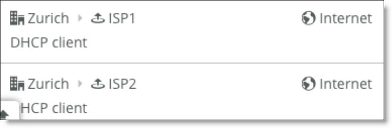
With this topology, you can implement the following configurations:
•Flow-distribution load-balancing traffic over the uplinks.
You create uplinks that belong to the same internet WAN.
Multiple internet uplinks
Every other connection is sent to a different uplink. AutoVPN is created on all uplinks.
There is no intelligence about the network conditions in terms of link utilization, packet drops, or latency. The system only monitors link availability.
•Prioritize one link over others.
You can set an AutoVPN priority for uplinks connected to the same WAN that determines the order in which they are used. For example, when you create two uplinks and set the first uplink to high priority and set the other to normal, SCM instructs the SteelConnect gateway to steer traffic over the tunnel(s) formed on the uplink with the highest priority.
Setting the AutoVPN priority
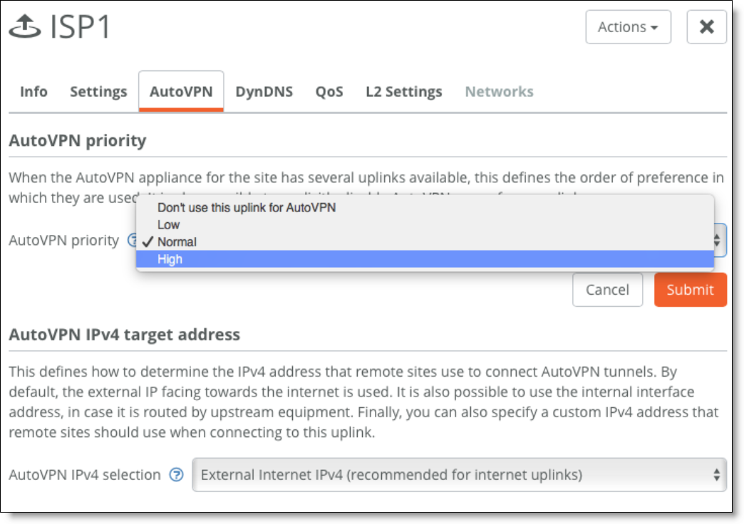
This priority applies to site-to-site traffic using the overlay (AutoVPN) only. Overlay tunnels are always formed. Internet traffic is load balanced over the different uplinks as long as its destined for the internet (by source address) or the same overlay VPN with equal priority (source/destination based).
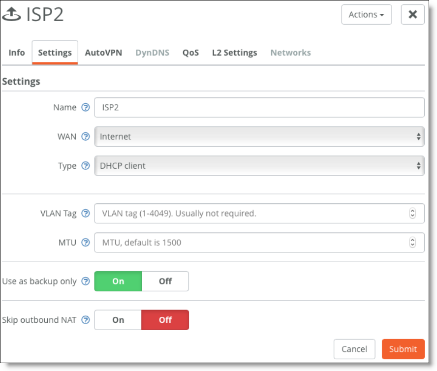
•Set up a master/backup.
Set up an uplink as a backup to be activated only when the other uplinks of a same WAN are unavailable.
Setting an uplink as a backup
•Define application-based traffic rules.
You can treat internet uplinks separately with traffic rules.
To define application-based traffic rules
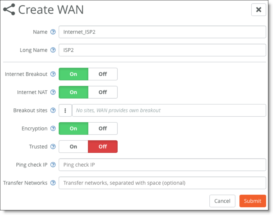
1. Create a new WAN type on SCM with the appropriate settings.
Creating a new WAN
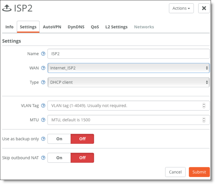
2. Configure the second uplink to be the same type as the new WAN created in Step 1: in that example, Internet_ISP2.
Configure the second uplink
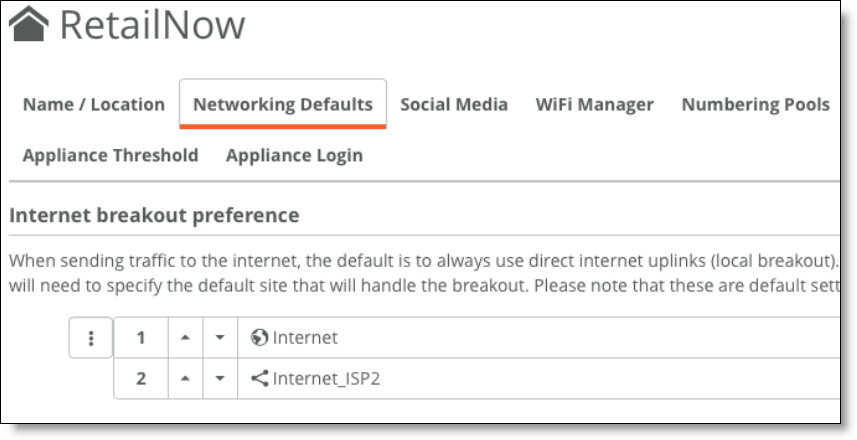
3. Update network preferences at the organization level and/or site level.
Note: This change impacts the traffic distribution for internet.
Network preferences
4. Choose Rules > Traffic Path rules and create traffic path rules to reflect your business logic.
You can set path preference and you can enable path quality options for site-to-site traffic through the overlay (AutoVPN) only.
Path quality and path preferences
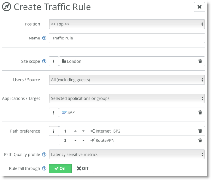
Traffic rules supersede internet and WAN preferences. For more details about traffic rules, see the SteelConnect Manager User Guide.
RouteVPN is the name for the overlay on an internet WAN uplink (and only for that type of WAN). With encryption enabled on the Internet_ISP2 WAN, an overlay tunnel is formed on top of uplinks of that type. Overlay tunnels are called AutoVPN on SteelConnect.
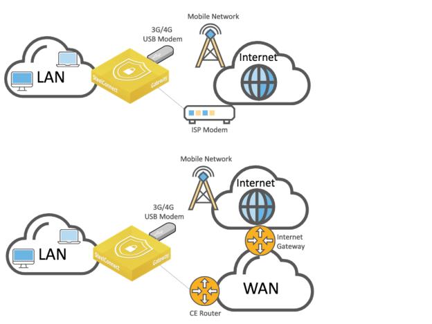
Secondary 3G/4G uplink
An alternative to a dual-homed internet topology is to rely on 3G/4G mobile connectivity through a USB LTE modem as a second active or backup uplink.
WAN topologies with 3G/4G uplink through USB port
You can configure SteelConnect appliances that have a USB port to support this topology.
SteelConnect 2.11 or later supports Inseego Skyus DS2 USB modem.
The following SteelConnect gateways support this topology.
SDI-VGW | SDI-130/130W | SDI-330 | SDI-1030 |
| | | |
To set up a topology with 3G/4G as a second or backup link
1. Configure a new uplink of type USB cellular.
Choose Network Design > Uplinks and click New Uplink to create an additional uplink for the site for the 4G connection.
New uplink for cellular traffic
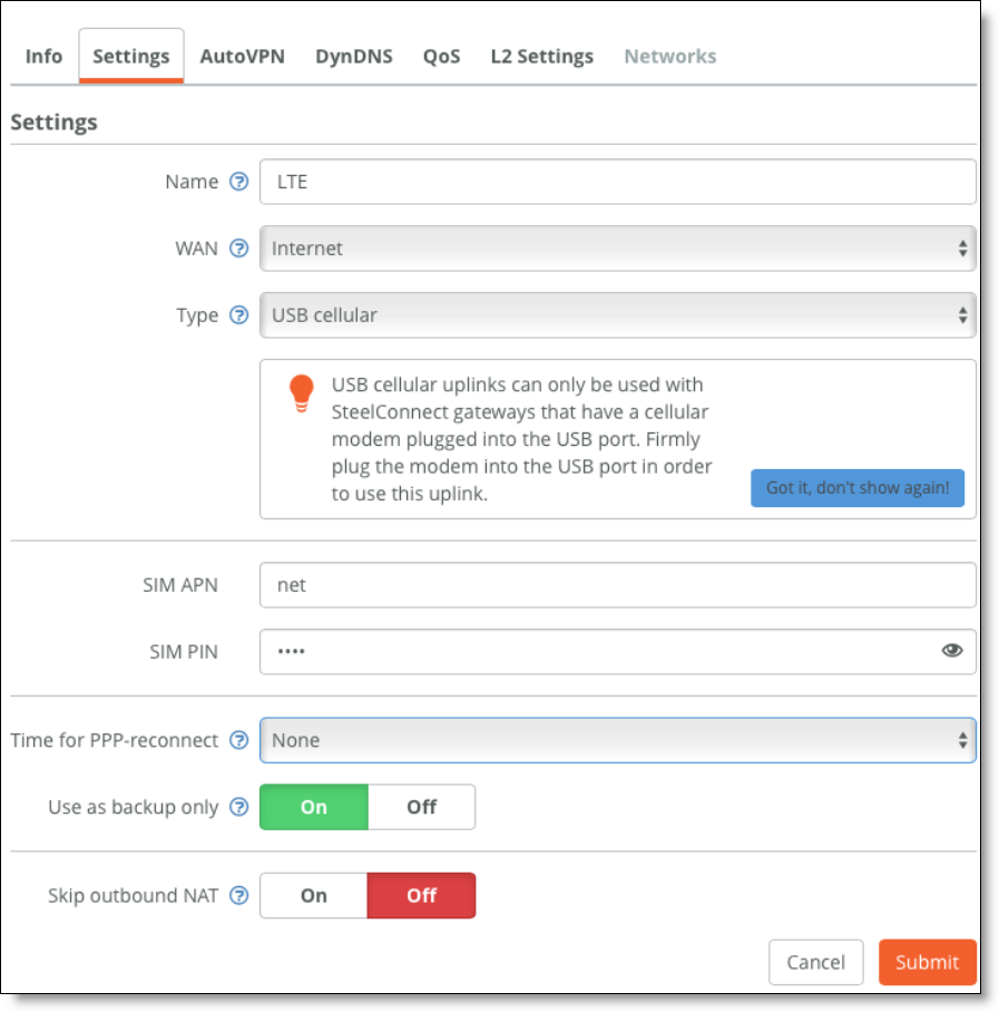
The default internet WAN is used for both uplinks—terrestrial and 3G/4G. Because the 3G/4G connection is expensive, it’s used as a backup only. This informs SCM not to auto load balance between the two available uplinks for the internet WAN. When enabled, the Use as backup only option enables this uplink only when the other uplink (default terrestrial uplink) is not working.
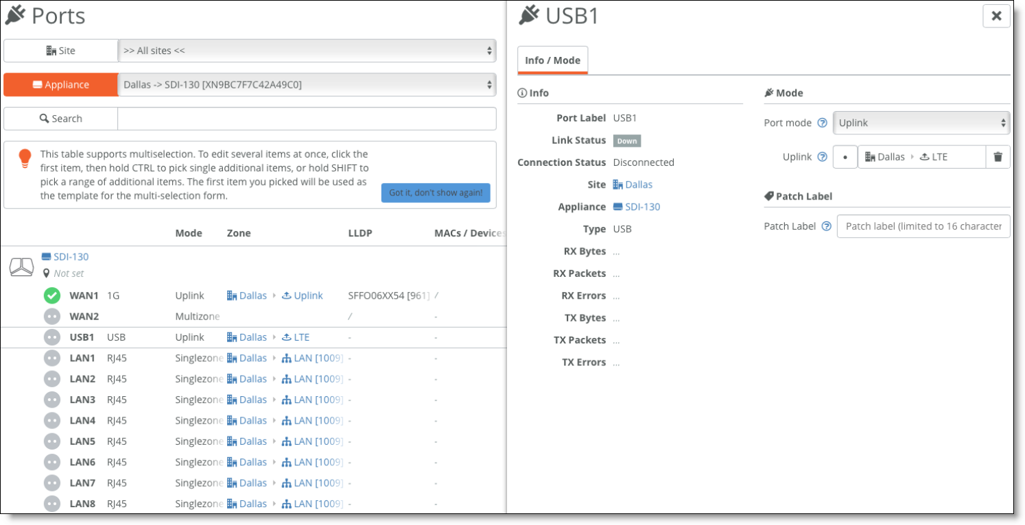
–The uplink is assigned to the USB port of the appliance.
Cellular uplink assigned to USB port
–If you don’t want to use the 4G uplink as backup only, but want to give it a lower priority, choose Network Design > Uplinks > AutoVPN and set the priority to normal.
Carrier charges might apply for cellular networks.
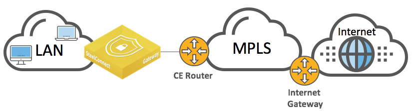
Integration with private networks
You can deploy SteelConnect gateways in private networks, such as MPLS. However, the gateways still require an internet breakout within the private network so the appliance can register and communicate with SteelConnect Manager.
When choosing the on-premises version of SteelConnect Manager, the appliance still needs to register with the core service.
To create a WAN integrated with a private network
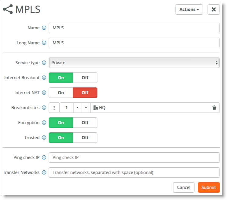
1. In SCM, choose Network Design > WANs to create an additional WAN. Click New WAN and configure these WAN settings:
–Set the Service Type to Private.
–Turn on Internet Breakout to indicate that this WAN can be used to transport traffic destined to the internet.
–It is not required to NAT the traffic. In some cases, such as when using proxies, it is not even recommended.
–Breakout sites - Select the headquarters (HQ) site to break all traffic by default over this MPLS WAN to the internet through the headquarters site. Keep in mind that the WAN selection can be overridden for specific sites, VLANs, or applications by traffic path rules.
–Turn on Encryption to create an additional overly network of VPN tunnels between internal zone-to-zone encrypted WAN traffic over noninternet uplinks. You can deploy an MPLS overlay that uses encryption and turn encryption off for another MPLS overlay.
–Turn on Trusted to permit all unencrypted traffic originating from a WAN to communicate into the WAN and LAN zones of the gateway. For example, this setting allows SteelConnect sites and legacy router sites within the WAN to communicate with each other. Instead of creating multiple inbound rules to permit trust, simply enable the Trusted setting. When enabled, all WAN transfer networks and eBGP learned networks are allowed to communicate into the gateway LAN zones.
Internet breakout configuration
In the WAN configuration, an important option for private networks is Ping Check IP. This configures an IPv4 address that checks the uplink status through ICMP ping. If left blank, it tries to reach 8.8.8.8 (a public IP address that belongs to Google). In the case of a large deployment, all gateways try to ping Google and if all traffic goes through a Central Internet Gateway, Google may throttle down or even blacklist the public IP address to prevent a potential DDOS attack. This would result in bad behavior of the MPLS uplink. Therefore, we recommended specifying an IP address of a stable equipment within the MPLS network.
Proxies in the internet breakout could potentially impact the behavior of the SteelConnect gateways. While a TCP proxy would not, SSL proxy would break the strong security model we have implemented to ensure strong authentication between the SteelConnect Manager and the gateways.
2. Add an uplink for your sites.
Keep in mind that SCM creates an uplink by default for your internet WAN but not for any additional WANs. You need to create these manually.
Creating an uplink for your internet WAN
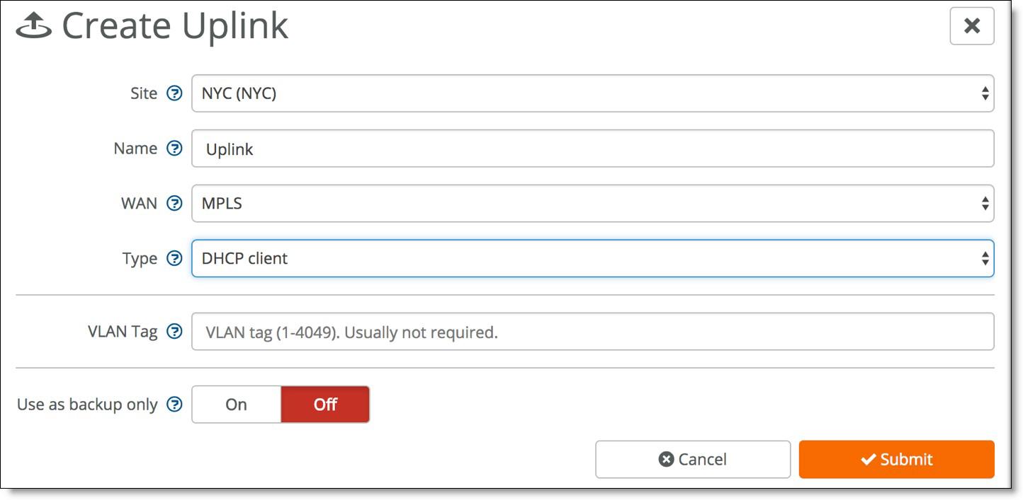
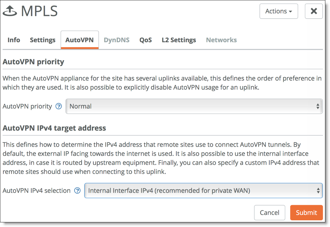
3. Set up AutoVPN over the MPLS network.
Configure the uplink of the gateway to propagate the internal IP address that the remote sites use as the endpoint target for the AutoVPN tunnel. By default, SCM uses the external IP address facing the internet. To configure an uplink to use an internal interface, select the uplink, select the AutoVPN tab, and choose Internal Interface IPv4 from the drop-down list.
Uplink AutoVPN settings
Integration with MPLS CE router
To ensure that the zones on the LAN side of the gateway can be reached, we recommend that you configure OSPF on the MPLS (CE) router. You could use static routes, but managing the static configurations becomes very time consuming as network routing choices expand, so we recommend OSPF instead.
WAN topology with MPLS CE router
A SteelConnect branch gateway supports OSPF version 2 in a broadcast network for dynamic routing. The gateway uses OSPF zone interfaces connected to LAN segments to learn routes dynamically from other routing devices.
The following SteelConnect gateways support this topology.
SDI-VGW | SDI-130/130W | SDI-330 | SDI-1030 |
| | | |
The SteelConnect gateway is not a strict ABR implementation as it can operate only within one OSPF area.
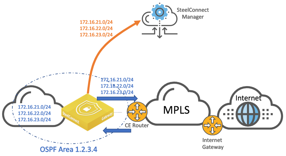
The SteelConnect gateway learns the subnets from the LAN and announces them to the CE router so the router knows how to reach those subnets and they get propagated to the MPLS network.
In addition, the SteelConnect gateway announces the LAN subnets to the SteelConnect Manager’s controller so they become part of the overlay network and can be propagated to other appliances in the same WAN.
The CE router announces the routes from the WAN to the SteelConnect Manager. The gateway places those routes in its underlay routing table so it can make decisions for sending traffic to legacy sites (non SD-WAN sites) or forming overlay tunnels with remote SD-WAN gateways.
WAN topology with MPLS CE router with OSPF area
To configure OSPF routing on a SteelConnect gateway on both the LAN and WAN side, you create an OSPF network, define a single area (or use an existing area), and attach a LAN-side zone and the uplink interface to the area. The basic steps to enable OSPF routing are:
–Select a site and create an OSPF network for that location that includes one area.
–Attach a zone and the uplink to the OSPF area.
OSPF network
To configure OSPF (or BGP) on an uplink, you must allocate a static IP address.
For additional OSPF details, refer to
Layer 3: Switch behind a SteelConnect gateway with OSPF dynamic routing and the
SteelConnect Manager User Guide. For more information about how to redistribute OSPF routes into BGP on routers, see the vendor documentation.
MPLS CE router replacement: ASBR-like deployment
In this topology, the SteelConnect gateway connects directly to the MPLS provider PE router. The gateway can replace a CE router to advertise and receive route announcements from the MPLS underlay.
WAN topology with MPLS CE router similar to ASBR
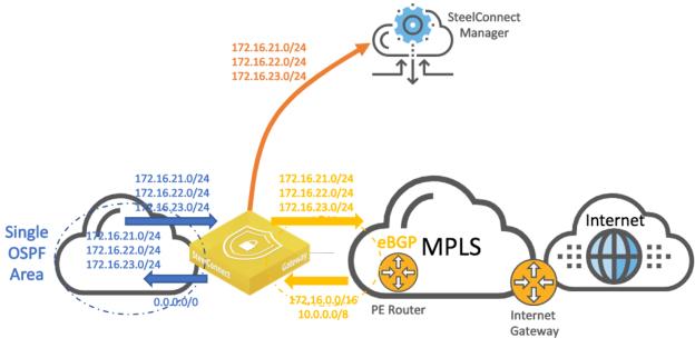
The SteelConnect gateway learns the subnets from the LAN and announces them to the PE router which will propagate them to the MPLS network.
If the default-originate option is enabled, the SteelConnect gateway announces a default route on the LAN side to attract all the traffic.
In addition, the SteelConnect gateway announces the LAN subnets to the SteelConnect Manager’s controller so they become part of the overlay network and can be propagated to other appliances participating in the same WAN.
The PE router announces the routes from the WAN to the SteelConnect gateway. The gateway places those routes in its underlay routing table so it can make decisions for sending traffic to legacy sites (non-SD-WAN sites) or forming overlay tunnels with remote SD-WAN gateways.
The following SteelConnect gateways support this topology.
SDI-VGW | SDI-130/130W | SDI-330 | SDI-1030 |
| | | |
SteelConnect gateways only support Ethernet handoffs.
To establish point-to-point connections between neighbors, you configure an eBGP session on a static IP uplink for a SteelConnect gateway and define its eBGP neighbor. Uplinks using DHCP don’t support eBGP.
To configure BGP routing
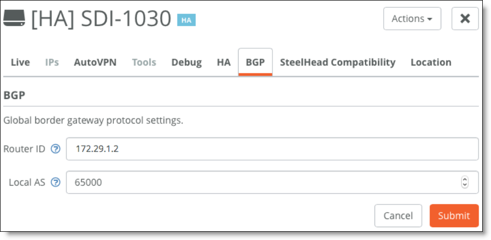
1. Select the branch gateway, choose Appliances, and select the BGP tab.
2. Fill out these required session attributes:
–Router ID - Specify the router IPv4 or IPv6 address to uniquely identify the SteelConnect gateway. This example uses the IPv4 address 172.29.1.2 for the uplink.
–Local AS - Specify the autonomous system (AS) number the SteelConnect gateway belongs to. This example uses the default setting of 65000.
Local AS setting
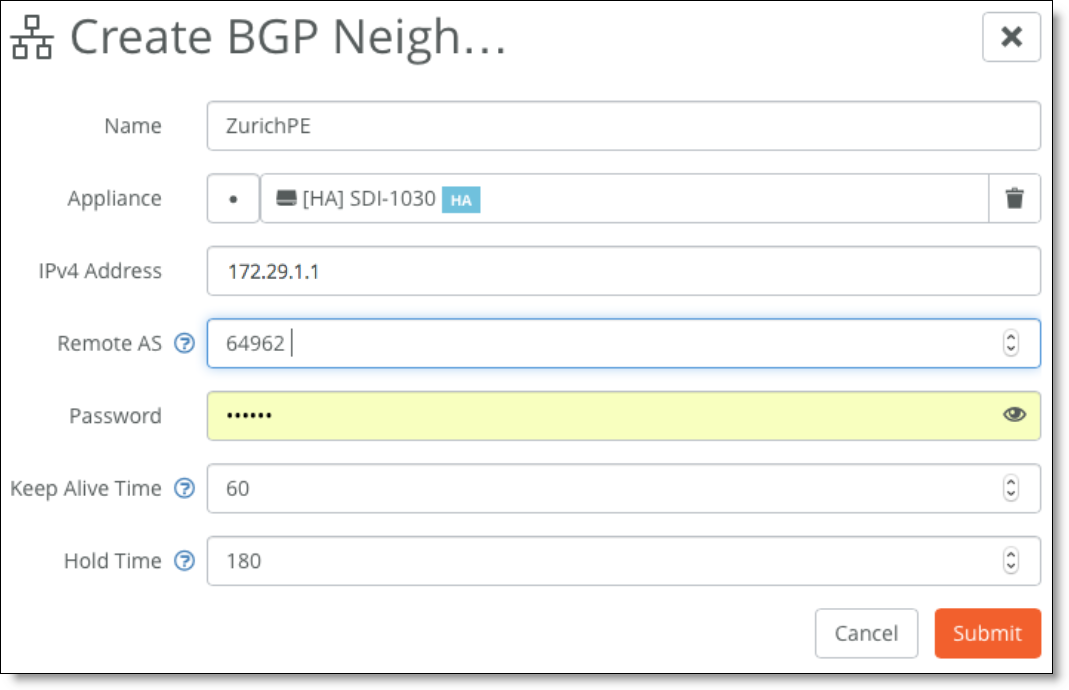
3. Create a new BPG neighbor under Network Design > Routing > BGP. Specify the following values:
–Name - Specify the peer name. Each uplink can support one eBGP peer.
–Appliance - Select the SteelConnect gateway appliance that acts as the CE router.
–IPv4 Address - Specify the peer router’s IPv4 address. This example uses 172.29.1.1.
–Remote AS - Specify the autonomous system number the peer belongs to. This example uses AS 64962 as the MPLS PE router belonging to the peer.
–Password - Type a password to enable MD5 authentication. You must use the same password on both BGP neighbors. If you don’t require MD5 authentication, you can leave this field blank.
–Keep Alive Time - Specify the amount of time, in seconds, that the eBGP neighbors exchange keepalive messages to determine whether a link has failed or is no longer available. The neighbors exchange keepalive messages often enough so that the hold time does not expire. The default setting is 60. Set this value to the value set on the PE router.
–Hold Time - Specify the amount of time, in seconds, that a gateway neighbor waits for an incoming keepalive, update, or notification message from a neighbor before it assumes its neighbor is down. If the gateway doesn’t receive a keepalive, update, or notification message from its neighbor within the period specified, it closes the connection and routing through that neighbor becomes unavailable. A 0 value means that no keepalive messages are sent and the connection will never close. The hold-time range is from 0 to 65535. The default setting is 180. Set this to the value set on the PE router. The hold-time value is three times the interval at which keepalive messages are sent. Using the default values for the keepalive time of 60 and the hold time of 180, the settings work together like this: after two neighbors establish an eBGP session, 60 seconds later they’ll each send a keepalive message. When a gateway receives a keepalive message from its neighbor, that gateway’s hold time for the session will have counted down from 180 to 120, but it’s then reset to 180. This process continues every 60 seconds. However, should neighbor A lose power, then neighbor B won’t receive any keepalives. So after 180 seconds, neighbor B determines that neighbor A is down and closes the session.
Creating a new BGP neighbor
4. Attach the uplink to BGP.
BGP uplink
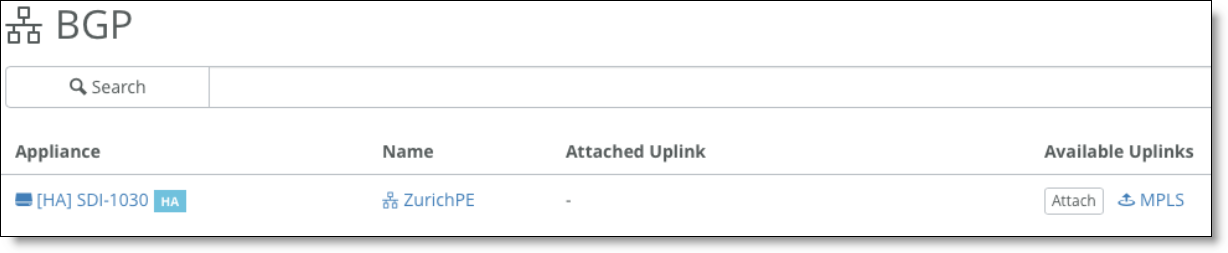
On the MPLS (PE) router, the following BGP configuration needs to be entered by your MPLS provider:
interface FastEthernet0/1
ip address 172.29.1.1 255.255.255.0
duplex auto
speed auto
!
router bgp 64962
bgp log-neighbor-changes
network 10.33.195.0 netmask 255.255.255.0
network 172.29.1.0
neighbor 172.29.1.2 remote-as 65000
no auto-summary
Through SCM, you enable SteelConnect gateways to use BGP to advertise all of their associated LAN zones (IP subnets) to an upstream router in the BGP environment of the MPLS provider. You need to create a routing policy to activate the ASBR functionality.
To configure a routing policy
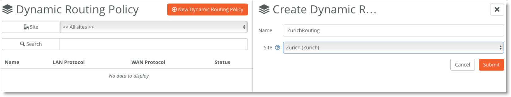
1. Choose Routing > Policy and create a new dynamic routing policy.
Creating a dynamic routing policy
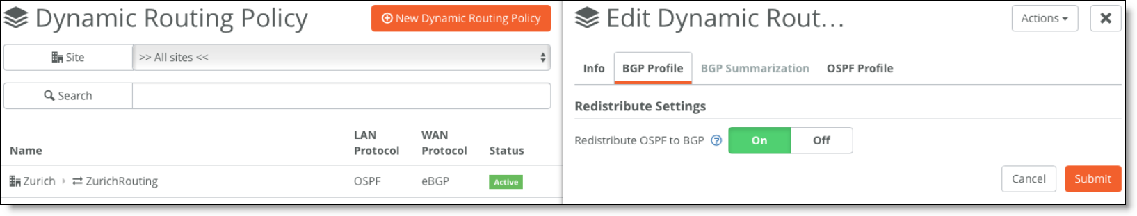
2. Redistribute OSPF to BGP to advertise the LAN zones (site subnets learned through OSPF) in the underlay.
Edit the policy, select the BGP Profile tab, and set Redistribute OSPF to BGP to On.
Editing the BGP profile
3. Add a default route in OSPF by enabling the feature under the OSPF Profile tab.
Adding a default route
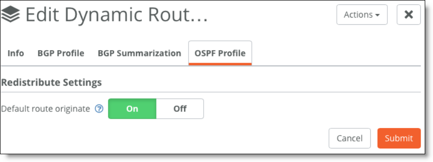
There is no BGP route injection into OSPF on SteelConnect gateways as opposed to a full ASBR implementation. The SteelConnect gateway will advertise 0.0.0.0/0 into OSPF.
4. You can summarize/aggregate routes in BGP under the BGP Summarization tab.
The gateway uses eBGP to advertise its LAN-side subnets into the MPLS AS.
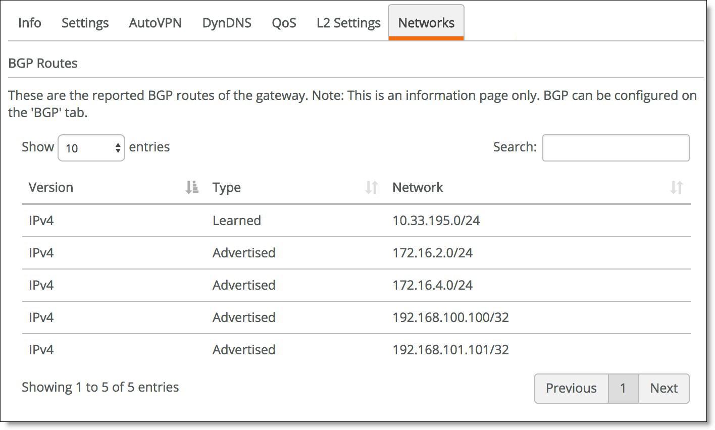
To view BGP learned and advertised routes
1. Choose Network Design > Uplinks.
2. Select the uplink with eBGP enabled.
3. Select the Networks tab.
The networks tab is dimmed when eBGP is not enabled on the gateway.
Viewing BGP routes of the gateway
The following table shows the route table scale supported on the WAN side for each gateway model.
SDI-VGW | SDI-130/130W | SDI-330 | SDI-1030 |
1000+ | 100+ | 100+ | 1000+ |
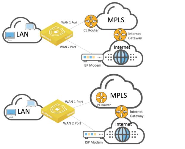
Hybrid WAN: internet and MPLS
As in the previous topologies, you connect a SteelConnect gateway to the routers by creating two WANs and two uplinks configured with different IP addresses. While SCM automatically creates the internet WAN and uplink, you need to add an uplink for the MPLS WAN after it is created, as explained in
Integration with MPLS CE router.
Internet and MPLS WAN topology
The following SteelConnect gateways support this topology.
SDI-VGW | SDI-130/130W | SDI-330 | SDI-1030 |
| | | |
SteelConnect can form VPN tunnels over both the default internet connection and the private MPLS WAN circuit. To set up a VPN over the MPLS network, turn encryption on when creating the WAN and configure the uplink to propagate the internal IP address that the remote sites use as the endpoint target for the AutoVPN tunnel.
For sites that have both circuits, there are two available encrypted tunnels (RouteVPN and MPLS) to choose from for inter-site traffic. You can set a default path preference for traffic under Organization > Networking Defaults.
WAN usage preference
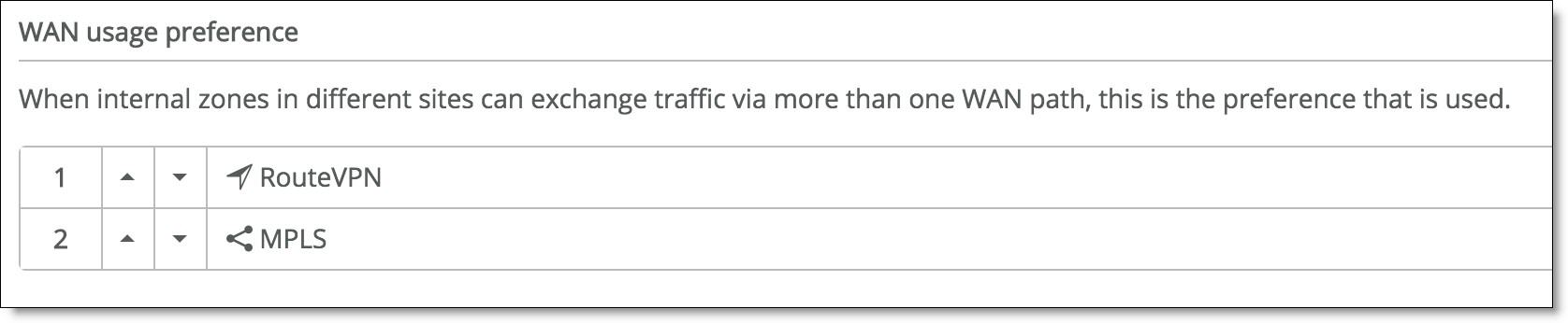
You can override the default path preference for an individual site, zone, user group, user, or application by going to the individual site and configuring it with a different rule. For example, to ensure that all of the VoIP traffic at the NYC site chooses the MPLS link over the RouteVPN, set the MPLS link to the number one path preference as shown in
Creating a path rule for the NYC site. This setting overrides the networking default for the organization as shown in
WAN usage preference.
Creating a path rule for the NYC site
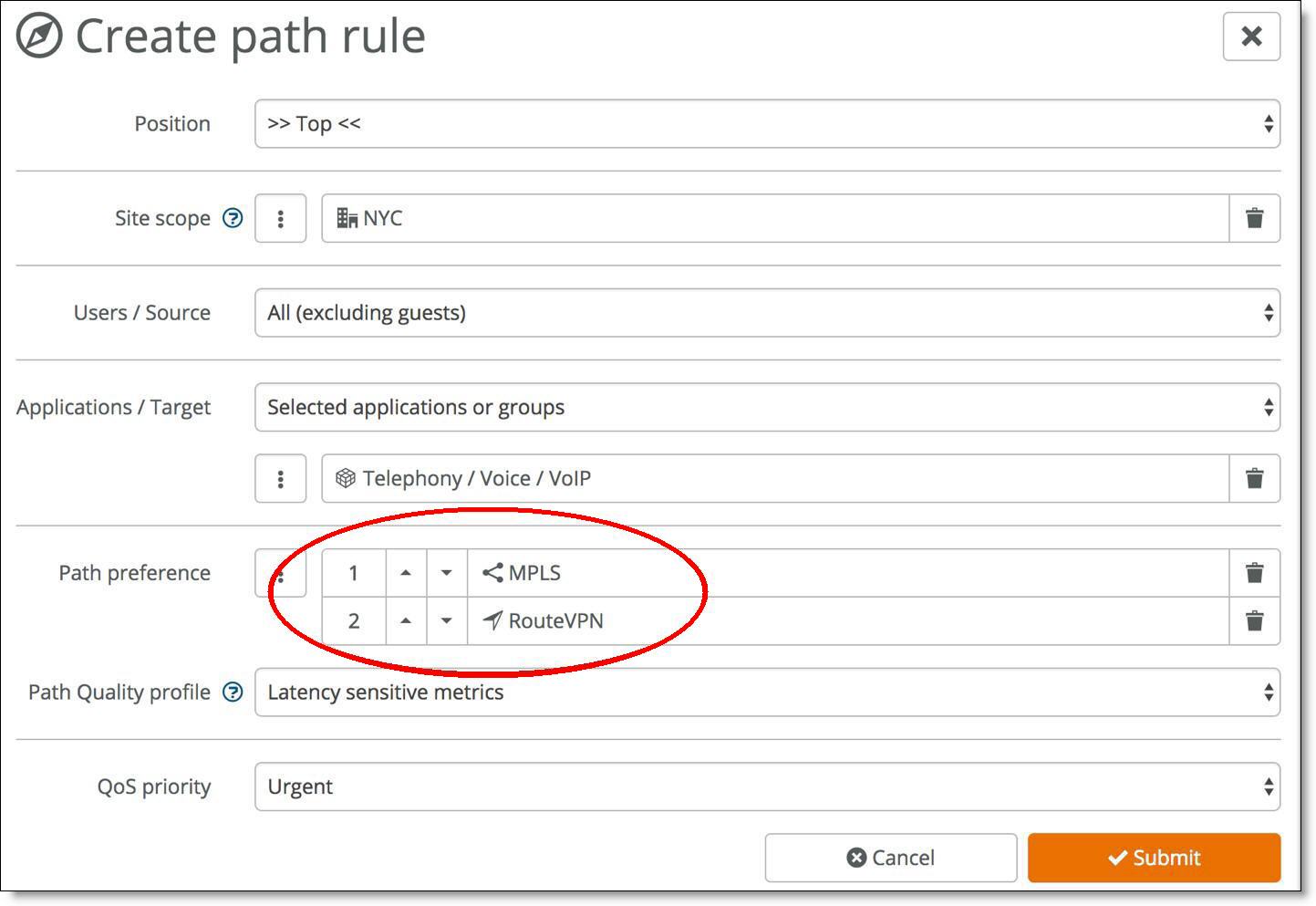
This rule now applies to all traffic for the NYC site. You can apply more granular rules using the other drop-down lists. See the traffic path rules topic in the SteelConnect Manager User Guide for more information.
If a specific topology like DC, Regional Hub and Spoke used in the network. There exist MPLS and
Internet uplink between DC and Regional Hub. Only Internet uplink between RegHub and Spoke.
Internet and MPLS WAN in a Hub and Spoke topology
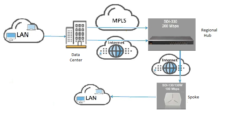
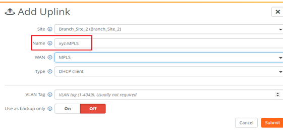
For the above-mentioned topology either of the two options can be opted
1. Append “-MPLS” keyword in the uplink name (only for MPLS WAN).
Important configuration information for specific hybrid WAN topology
2. In WAN usage preference, priority should be set to RouteVPN.
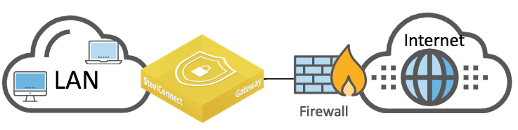
Integration with WAN-facing firewall
This topology includes a firewall on the WAN side of the SteelConnect gateway, as shown in
SteelConnect gateway with firewall.
SteelConnect gateway with firewall
The following SteelConnect gateways support this topology.
SDI-VGW | SDI-130/130W | SDI-330 | SDI-1030 |
| | | |
To allow the gateway to form an AutoVPN tunnel to the site across the firewall from the other sites, you create a rule to allow inbound connections on UDP port 4500.
In addition, the SteelConnect gateway needs to ping externally and access SteelConnect services on the internet. The following table shows common services and connection ports.
Service | Outbound connection port |
DNS | UDP 53 |
NTP | UDP 123 |
Uplink IP Reflector | TCP 80 |
SteelConnect Manager | TCP 443 |
Configuration/API | TCP 3900 |
SSH Proxy | TCP 3903 |
Tunneled SSH | TCP 3904 |
Reporting | TCP 3905 |
For a full list of connection ports that SteelConnect uses, see the “SteelConnect Connection Ports” topic in the SteelConnect Manager User Guide.
Highly secured WAN
Some customers operate highly secured WAN where only the LAN is trusted. All traffic coming from either the MPLS network and, of course, the internet is not trusted. Traffic can be encrypted by the firewalls on MPLS.
Highly secured topology with firewalls
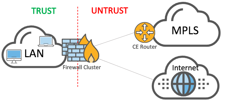
For such a topology, we recommend you leverage virtualization capabilities of the firewalls. For example, Fortinet calls it Virtual Domains (VDOM), Palo Alto Networks uses Virtual Systems, and Cisco has Virtual Context.
The concept has hardware firewall appliances operating one or more logical firewalls independently from each other. Each logical firewall performs specific operations.
The following SteelConnect Manager gateways support this topology.
SDI-VGW | SDI-130/130W | SDI-330 | SDI-1030 |
| | | |
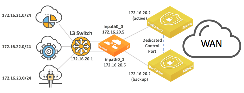
A possible implementation of SteelConnect in that context appears in the following deployment diagram.
Highly secured topology with logical firewalls
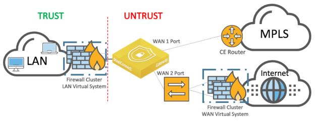
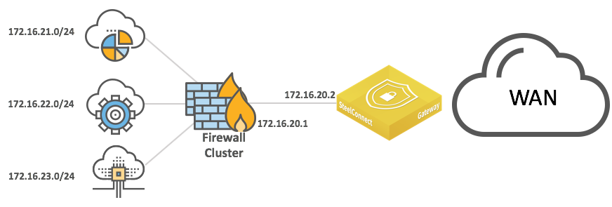
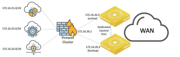
The SDI-130 and SDI-330 gateways have only two WAN ports so they require a switch in this example to connect the SteelConnect gateway to a firewall cluster.
You can configure the SDI-VGW and SDI-1030 gateways to use up to seven WAN ports. In that case, the LAN Virtual System considers all WAN-facing interfaces as untrusted. All traffic transported by SteelConnect overlays will be analyzed by this firewall.
The WAN Virtual System protects the site from internet threats and lets a SteelConnect gateway forming IPsec tunnels (RouteVPN or standard IPsec communications) on the internet.
The gateway creates overlay tunnels (AutoVPN) on MPLS between SteelConnect-equipped sites.
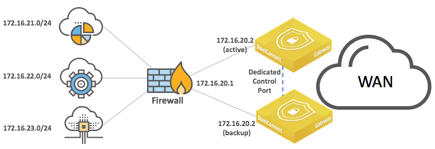
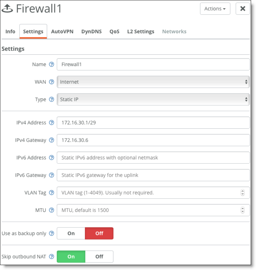
To connect SDI-1030 to a firewall cluster (active/backup)
1. Create two internet uplinks that belong to the same internet WAN, have IP addresses in the same subnet, and point to the same gateway IP address (Firewall VIP).
Set the first uplink to active. (Ensure Use as backup only is set to Off.)
First firewall uplink
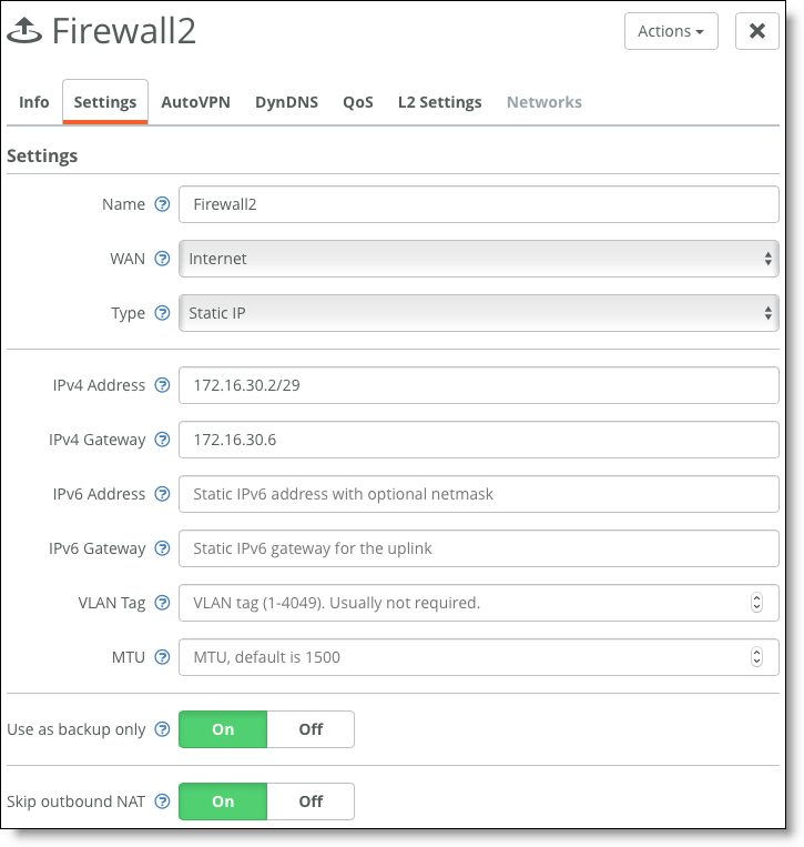
2. Configure the second uplink as a backup. (Ensure Use as backup only is set to On.)
Second firewall uplink
Consider the migration strategy: for communication with sites that are not yet equipped with SteelConnect, you can keep creating IPsec tunnels with the Firewalls cluster. Alternatively, you can create IPsec tunnels between a SteelConnect gateway and the remote firewall using the Classic VPN feature.
WAN-side high availability
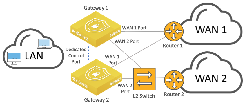
For complete end-to-end physical and path redundancy, we recommend that you deploy multiple (multihomed) upstream WAN devices along with multiple gateways at the site.
HA gateways connected directly to WAN edge routers, each router has multiple WAN-side ports
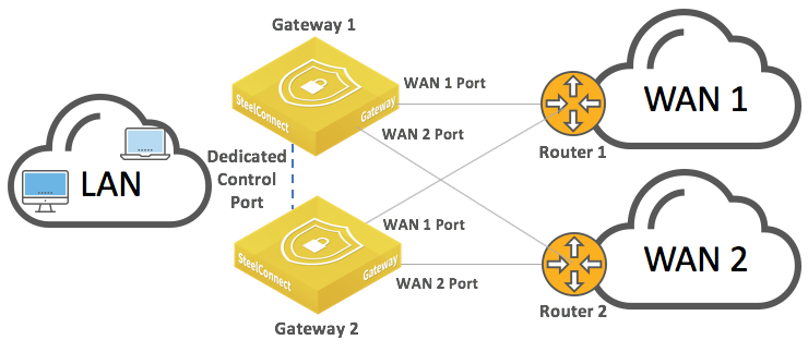
Supported high-availability WAN configurations include MPLS, internet breakout, and VLAN. The SteelConnect HA gateways operate in active/passive mode: the master gateway processes traffic while the backup gateway remains in standby mode, ready to take over if the master gateway fails.
The following SteelConnect Manager gateways support this topology.
SDI-VGW | SDI-130/130W | SDI-330 | SDI-1030 |
| | | |
SteelConnect gateways do not support asymmetric HA. If you need asymmetric HA, we recommend SteelHead SD.
In this sample topology, the WAN routers have at least two LAN-facing ports so we can attach each SteelConnect gateway to both routers. IP addresses will be configured on the router LAN interfaces.
The sample topology uses these IP addresses:
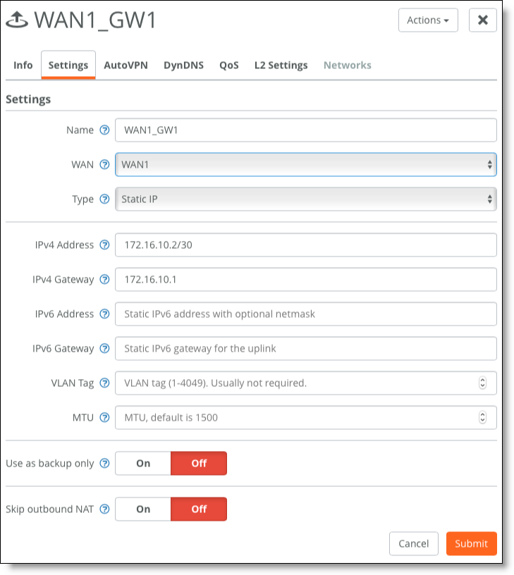
•Router 1's LAN interface 1: 172.16.10.1/30
•Router 1's LAN interface 2: 172.16.10.5/30
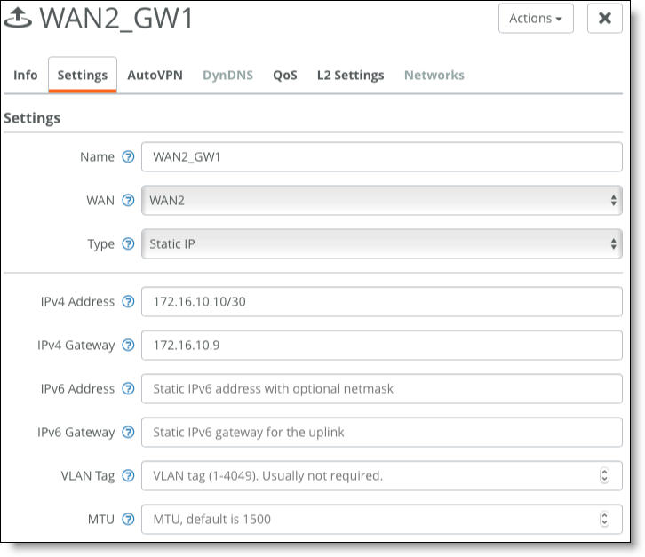
•Router 2's LAN interface 1: 172.16.10.9/30
•Router 2's LAN interface 2: 172.16.10.13/30
It is not possible to name a gateway, so to clearly distinguish among gateways, enter a unique location in the Location field under the Location tab for the gateway. See the SteelConnect Manager User Guide for details.
To configure WAN-side HA for this sample topology
1. For Gateway 1, configure an uplink to WAN1.
Choose Network Design > Uplinks > Add Uplink.
WAN1 uplink for Gateway 1
2. Configure an uplink to WAN2.
WAN2 uplink for Gateway 1
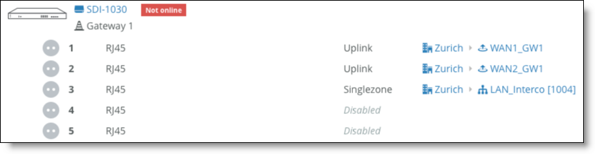
3. Assign uplinks to ports.
Choose Appliances > Ports and select Gateway 1.
Assign uplinks to ports
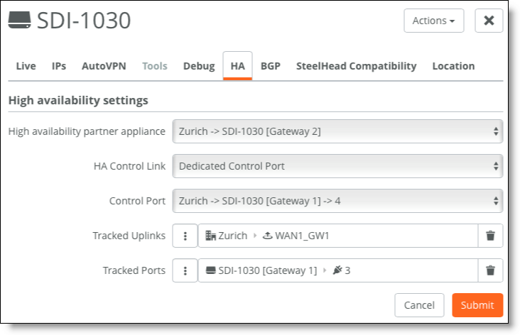
4. Configure high availability.
Choose Appliances > Overview and select Gateway 1. In the HA tab, select Gateway 2 as the HA partner.
Configure HA
Failover is triggered when:
–all uplinks attached to the gateway fail
–the gateway appliance fails
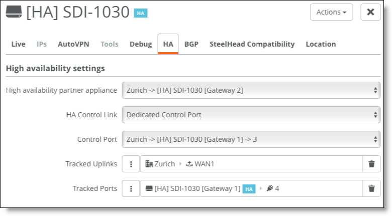
If a specific uplink is critical to site performance, failover can be triggered by the Tracked Uplinks setting. If the connection between Gateway 1 and Router 1 fails because of a cable or configuration error, SteelConnect can failover to Gateway 2.
As explained in the LAN topologies section, it is possible to track LAN ports to trigger the failover using the Tracked Ports setting.
5. For Gateway 2, configure an uplink to WAN1.
Choose Network Design > Uplinks > Add Uplink.
WAN1 uplink for Gateway 2
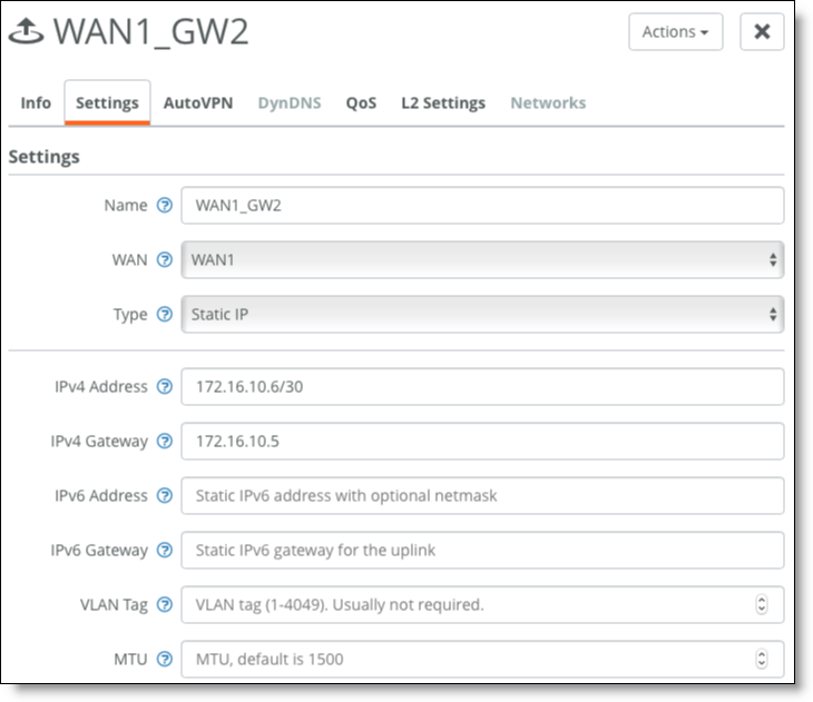
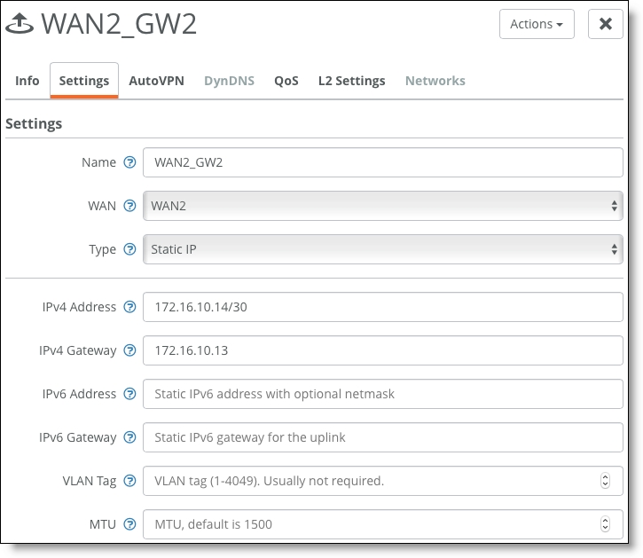
6. Configure the uplink to WAN2.
WAN2 uplink for Gateway 2
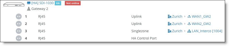
7. Assign uplinks to ports.
Choose Appliances > Ports and select Gateway 2.
Assign uplinks to ports
High availability with one LAN-facing port on WAN routers
Some WAN routers might have only a single LAN-facing port. In this case, use a switch to connect the two gateways to the WAN, as shown in
HA gateways connected to WAN edge routers - one directly, the other through a switch. If the WAN is an internet WAN, your ISP can provide a modem with switched ports.
HA gateways connected to WAN edge routers - one directly, the other through a switch
If all routers have only a single LAN-facing port, as shown in
HA gateways connected to a switch connected to multiple routers, configure the backup gateway with mirrored uplinks. That ensures that the master gateway configuration is mirrored on the backup gateway. The switch is configured with standard access ports.
HA gateways connected to a switch connected to multiple routers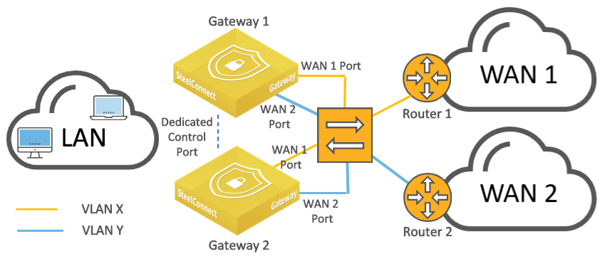
The following SteelConnect Manager gateways support this topology.
SDI-VGW | SDI-130/130W | SDI-330 | SDI-1030 |
| | | |
For our sample configuration, assume that both routers have only one LAN facing port and the switch has a standard access port configuration. Our sample topology will use the following IP addresses:
•Router 1 LAN interface: 172.16.10.1/30
•Router 2 LAN interface: 172.16.10.5/30
To configure HA for a LAN-facing port on WAN routers with our sample configuration
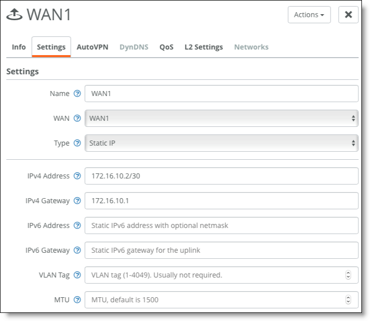
1. For Gateway 1, configure an uplink for WAN1.
Choose Network Design > Uplinks > Add Uplink.
WAN1 uplink for Gateway 1
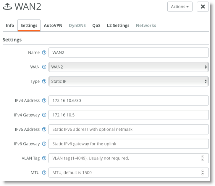
2. Configure an uplink to WAN2.
WAN2 uplink for Gateway 1
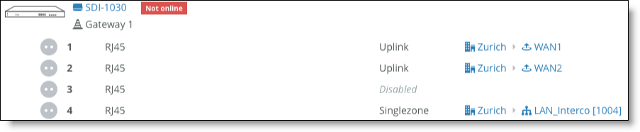
3. Assign uplinks to ports.
Choose Appliances > Ports and select Gateway 1.
Assign uplinks to ports
4. Configure high availability.
Choose Appliances > Overview and select Gateway 1. In the HA tab, select Gateway 2 as the HA partner.
Configure HA
5. Configure Gateway 2.
Because both WAN routers have only one LAN-facing port, we need to configure the Gateway 2 ports using mirrored uplinks so the configuration of Gateway 1 will be mirrored on Gateway 2.
To configure mirrored uplinks
1. In SCM, choose Appliances > Ports.
2. Find the backup gateway and select one of its ports. The port you select should be identical to one of the ports you configured on the master gateway. For example, if you configured port WAN1 and port WAN2 on the master gateway, select either port WAN1 or port WAN2.
3. In the Info/Mode tab on the port details page, select Mirrored Uplink from the Port Mode drop-down list.
Mirrored uplinks
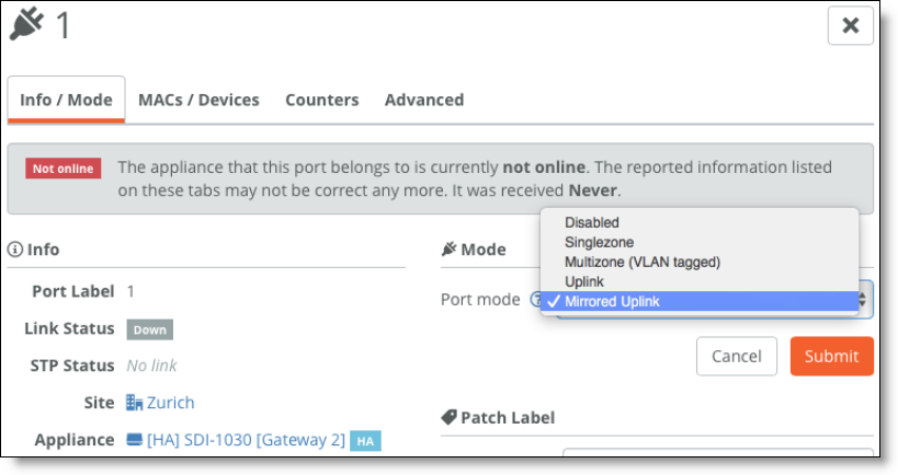
4. Click Submit.
5. Repeat steps 1 through 4 for the other port.
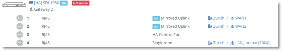
6. Close the port details page. On the Ports page, a blue HA icon appears next to the words Mirrored Uplink under the Mode column for the ports you configured.
Port details
For more information about high availability and mirrored ports, see the “Configuring High Availability” chapter in SteelConnect Manager User Guide.