Replacing SteelHead GX, xx70, Interceptor 9600, SteelFusion Core 3500 Components
This chapter describes how to replace components in SteelHead GX10000, CX xx70, SteelCentral xx70, SteelHead Interceptor 9600, and SteelFusion Core 3500 appliances. It includes these sections:
Appliances included in this chapter
This chapter describes how to replace components in the following appliances:
• 1U xx70 appliances, including SteelHead CX3070, SteelCentral NetExpress 470, SteelCentral NetProfiler 4270-DB/UI/DP, SteelCentral Flow Gateway 2270, SteelCentral NetShark 2170, and SteelCentral AppResponse 2170.
• 2U GX10000 appliances.
• 2U xx70 appliances, including SteelHead CX5070, SteelHead CX7070, SteelCentral NetProfiler 2270, SteelCentral NetProfiler 4270-EX, SteelCentral NetProfiler 4270-AN, SteelCentral NetShark 4170, SteelCentral NetShark 6170, and SteelCentral AppResponse 4170, SteelCentral AppResponse 6170, and SteelCentral AppResponse 8170.
• 2U SteelHead Interceptor 9600 appliances.
• 2U SteelFusion Core 3500 appliances.
Required tools
You need the following tools and equipment to replace appliance components:
• You must use approved components for the appliance to function properly. Installation of unapproved components will result in boot failure. To order components, contact Riverbed Support at https://support.riverbed.com.
• An antistatic strap. When you replace appliance components, you must wear a grounded ESD antistatic strap to protect the hardware against electrostatic discharge. Make sure that the strap makes skin contact prior to handling equipment.
• Use the magnetic Phillips screwdriver enclosed with your shipment to remove screws in the appliance. The magnetic screwdriver ensures screws aren’t lost in the appliance.
Removing and installing the bezel
This procedure describes how to remove and install the front bezel on 1U and 2U GX and xx70 appliances.
To remove the bezel
1. If locked, unlock the bezel.
Figure: Removing the bezel on 1U and 2U GX and xx70 appliances

Note: The bezel that ships with your appliance might look different from the bezel in the figure.
To install the bezel
Before installing the bezel, you must install the rack handles.
3. Lock the bezel, if needed.
Figure: Installing the bezel on 1U and 2U GX and xx70 appliances

(xx70 shown)
Removing and installing the chassis cover
You need to remove the top cover to add or replace components inside the appliance. This section describes how to work with the chassis cover on GX and xx70 appliances.
The appliance must be operated with the appliance cover in place to ensure proper cooling.
Removing the chassis cover on 1U and 2U appliances
This section describes how to remove the chassis covers for the 1U and 2U GX and xx70 appliances.
To remove the chassis cover on 1U and 2U appliances
1. Power down the appliance and unplug all peripheral devices and the power cable.
2. Perform one of the following actions:
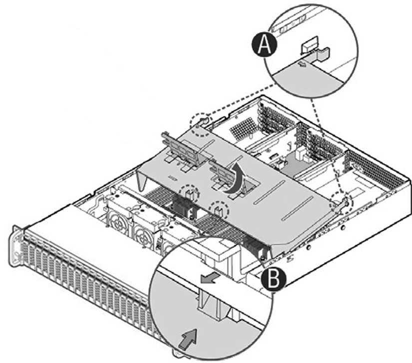
Figure: GX10000 removing the appliance cover

• For all other 2U appliances, remove the four screws (letter A). If your appliance doesn’t have screws on the cover, go to the next step.
Figure: Removing the 1U appliance cover

• Place your thumbs on the recessed tabs (letter B) and slide the cover straight back.
Installing the chassis cover on 1U and 2U appliances
This section describes how to install the chassis covers for the 1U and 2U GX and xx70 appliances.
To install the chassis cover on 1U and 2U appliances
1. Perform one of the following actions:
• For GX10000 appliances, place the top cover on the appliance and slide it toward the front of the chassis until the recessed front edge fits smoothly under the chassis edge and the locking pins (see
Figure: GX10000 installing the appliance cover letter B) are fully engaged.
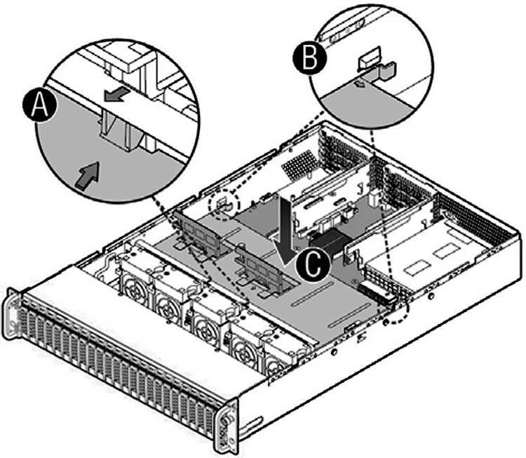
Figure: GX10000 installing the appliance cover
• For all other 2U appliances, place the top cover on the appliance and slide it toward the front of the chassis until the recessed front edge fits smoothly under the chassis edge and the locking pins (see
Figure: Installing the appliance cover (1U shown), letter A) are fully engaged. If your appliance doesn’t require screws, the installation is complete.
Figure: Installing the appliance cover (1U shown)

Removing and installing the air duct
The appliances in this chapter require an air duct for proper airflow. Always operate your appliance with the air duct in place.
You need to remove the air duct to access many internal components.
Removing and installing the air duct for 1U appliances
Follow these instructions to remove and install the air duct for the 1U appliances.
To remove the air duct in 1U appliances
• Lift the air duct straight up.
Figure: Removing the air duct

To install the air duct in 1U appliances
• Ensure the HDD cable is inside the air duct, align the two holes on the air duct with the alignment pins on the chassis, and lower the air duct into place.
Figure: Installing the air duct

Removing and installing the air duct for 2U appliances
Follow these instructions to remove and install the air duct for the 2U appliances.
To remove the air duct in 2U appliances
1. For SteelHead GX, CX, SteelHead Interceptor 9600, and SteelFusion Core 3500, unplug the cables on the SSD boot drive.
Figure: Unplugging the SSD drive cable
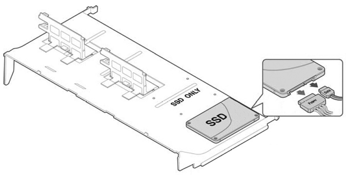
Figure: Removing the air duct
To install the air duct in 2U appliances
Figure: Installing the air duct
4. For SteelHead GX, CX, SteelHead Interceptor 9600, and SteelFusion Core 3500, plug in the SSD boot drive cable.
Replacing disk drives
This section describes how to remove and replace disk drives in the SteelHead GX10000, SteelHead CX xx70, SteelCentral xx70, SteelHead Interceptor 9600, and SteelFusion Core 3500 appliances.
This section includes the following procedures:
Note: If you need to replace an appliance, you can’t move the disks to preserve your data. Each disk is encoded with machine-level information and moving disks isn’t supported.
Replacing disk drives in 1U appliances with 3.5-inch drives
SteelHead CX3070, SteelCentral NetExpress 470, SteelCentral NetProfiler 4270DP, SteelCentral Flow Gateway 2270, and SteelCentral NetShark 2170 appliances are equipped with replaceable, hot-swappable 3.5-inch hard-disk drives (HDD). SteelHead CX3070 appliances include HDDs and solid-state drives (SSD). SteelCentral NetProfiler 4270DB/UI includes SSDs.
When replacing a drive, replace only one drive at a time. You must use approved disk drives. To order disk drives, contact Riverbed Support at https://support.riverbed.com.
Note: When you replace disk drives, you must wear a grounded ESD antistatic strap to protect the hardware against electrostatic discharge. Make sure that the strap makes skin contact prior to handling equipment.
Caution: 
Use caution when you remove or replace appliance components; they can become hot to the touch.
To replace the disk drive in 1U appliances
1. Remove the bezel.
2. Identify the faulty disk drive.
The web interface identifies the faulty disk drive. On a SteelHead, the Alarm Status page in the Management Console identifies the faulty drive.
The disk drive LED is orange for failed drives.
The drives are numbered in ascending order from left to right (that is, 0, 1, 2, 3).
– SteelHead CX3070 HDDs can be in slots 0 and 1; SSDs can be in slot 2 and 3.
– SteelCentral NetProfiler 4270-DB/UI have SSDs in slots 0 and 1.
– SteelCentral NetProfiler 4270-DP has HDDs in slots 0 and 1.
– SteelCentral NetExpress 470 has 4-TB drives in slots 0 and 1 and 2-TB drives in slots 2 and 3.
– SteelCentral Flow Gateway has 1-TB HDDs in slots 0 and 1.
– SteelCentral NetShark 2170 has 2-TB SATA drives in slots 0 and 1 and 4-TB SATA drives in slots 2 and 3.
– SteelCentral AppResponse 2170 has 2-TB SATA drives in slots 0 and 1 and 4-TB SATA drives in slots 2 and 3.
Figure: Disk drive numbers

3. Press the orange release button and pull the drive handle toward you (letter A and B).
Figure: Removing the disk drive

4. Slide the faulty disk drive out of the slot.
5. Remove the four screws securing the drive from the carrier and remove the failed drive (letter C).
Figure: Removing the drive from the carrier

Make sure the drive connector matches the backplane connector.
Figure: Inserting the drive in the carrier

7. Open the new disk-drive handle by pressing the orange release button.
8. Slide in the new disk drive until it mates with the back connectors in the chassis (see
Figure: Inserting the disk drive, letter E and F). The disk drive LED lights blue when connected.
Figure: Inserting the disk drive

9. Press in the disk-drive handle to close.
The new disk drive runs through a self-test automatically. The disk drive automatically begins proper operation with the other disk drives. You don’t need to set up or configure the new disk drive.
Note: When replacing drive 2 or 3 on a NetShark 2170, Packet Storage appears as Inoperable in the NetShark Web interface Status page. Choose System > Maintenance; the new HDD is labeled New. Click Reinitialize Packet Storage to restore operation.
Important: It takes approximately 3 to 4 hours, depending on the system load, to rebuild a new disk drive. You can configure the system to send an email to the administrator user when the disk drive has finished rebuilding.
Replacing disk drives in 2U appliances with 2.5-inch drives
2U SteelHead GX10000, CX (CX5070 and CX7070), and SteelHead Interceptor 9600 appliances are equipped with replaceable, hot-swappable 2.5-inch drives.
When replacing a drive, replace only one drive at a time. You must use approved disk drives. To order disk drives, contact Riverbed Support at https://support.riverbed.com.
Note: When you replace disk drives, you must wear a grounded ESD antistatic strap to protect the hardware against electrostatic discharge. Make sure that the strap makes skin contact prior to handling equipment.
Caution: Use caution when you remove or replace components; they can become hot to the touch.
To replace a 2.5-inch disk drive in the 2U appliances
1. Remove the bezel.
2. Identify the faulty disk drive.
The web interface identifies the faulty disk drive. On a SteelHead, the Alarm Status page in the Management Console identifies the faulty drive.
The disk drive LED is orange for failed drives.
The drives are numbered in ascending order from left to right (that is, starting with 0 on the left and ending with 23 on the right).
– For the SteelHead GX10000 appliances, disks 0 and 24 are HDDs and disks 1 through10 are SSDs.
– For the CX appliances, disks 0 and 23 are HDDs and disks 1 through 22 are SSDs.
– For the Interceptor 9600 appliances, disks 0 and 23 are HDDs.
Figure: Disk drive number

s
3. Press the release button and pull the drive handle toward you to release the disk drive (letter A).
Figure: Releasing the disk drive

4. Slide the faulty disk drive out of the slot (letter B).
Figure: Remove the disk drive

5. Remove the four screws securing the drive from the carrier and remove the failed drive (letter C).
Figure: Removing the drive from the carrier

Make sure the drive connector matches the backplane connector.
Figure: Inserting the drive in the carrier

7. Open the new disk-drive handle by pressing the release button.
8. Slide in the new disk drive until it mates with the back connectors in the chassis (see
Figure: Inserting the disk drive, letter E). The disk drive LED lights blue when connected.
9. Press in the disk-drive handle to close.
Figure: Inserting the disk drive

The new disk drive runs through a self-test automatically. The disk drive automatically begins proper operation with the other disk drives. You don’t need to set up or configure the new disk drive.
Replacing disk drives in 2U appliances with 3.5-inch drives
2U SteelFusion Core 3500, SteelCentral NetProfiler (2270, 4270-EX, and 4270-AN), SteelCentral 4170, 6170, and 8170 appliances and SteelCentral Storage Units (48 TB and 72 TB) are equipped with replaceable, hot-swappable 3.5-inch HDDs.
When replacing a drive, replace only one drive at a time.
You must use approved disk drives. To order disk drives, contact Riverbed Support at https://support.riverbed.com.
Note: When you replace disk drives, you must wear a grounded ESD antistatic strap to protect the hardware against electrostatic discharge. Make sure that the strap makes skin contact prior to handling equipment.
Caution: Use caution when you remove or replace components; they can become hot to the touch.
To replace a disk drive in 2U appliances with 3.5-inch drives
1. Remove the bezel.
2. Identify the faulty disk drive.
The web interface displays an alarm that identifies the faulty disk drive.
The disk drive LED is orange for failed drives.
– SteelFusion Core 3500 has 1-TB HDD drives in slots 0 to 3 and 80-GB SSDs in slots 4 and 5.
– NetShark 4170 has 2-TB SATA drives in slots 0 to 3 and 4-TB SATA drives in slots 4 to 11.
– NetShark 6170 has 2-TB SATA drives in slots 0 to 3.
– SteelCentral NetProfiler 2170 has 2-TB drives in slots 0 to 11.
– SteelCentral NetProfiler 4270-EX and 4270-AN have 4-TB drives in slots 0 to 11.
– SteelCentral AppResponse 4170 has 2-TB SATA drives in slots 0 to 3 and 4-TB SATA drives in slots 4 to 11.
– SteelCentral AppResponse 6170 has 2-TB SATA drives in slots 0 to 3.
– SteelCentral AppResponse 8170 has 2-TB SATA drives in slots 0 to 3.
Figure: Disk drive numbers

3. Press the orange release button and pull the drive handle toward you to release the disk drive (letter A and B).
Figure: Releasing the disk drive

4. Slide the faulty disk drive out of the slot.
5. Remove the four screws securing the drive from the carrier and remove the failed drive (letter C).
Figure: Removing the drive from the carrier
Make sure the drive connector matches the backplane connector.
Figure: Inserting the drive in the carrier
8. Slide in the new disk drive until it mates with the back connectors in the chassis. The disk drive LED lights blue when connected.
Figure: Inserting the disk drive

9. Press in the disk-drive handle to close.
The new disk drive runs through a self-test automatically. The disk drive automatically begins proper operation with the other disk drives. You don’t need to set up or configure the new disk drive.
Note: When replacing a drive on a NetShark 4170, NetShark 6170, or Storage Unit, Packet Storage appears as Inoperable in the NetShark web interface Status page. Choose System > Maintenance; the new HDD is labeled New. Click Reinitialize Packet Storage to restore operation.
Replacing power supply units
This section describes how to replace a power supply in 1U and 2U appliances. These appliances are equipped with replaceable, hot-swappable power supply units.
Caution: Use caution when replacing the power supply units; they can become hot to the touch.
To replace power supply units in 1U and 2U appliances
1. Locate the defective power supply unit and remove the power cord.
2. Press the release tab toward the black handle, and pull the power supply unit toward you.
Figure: Removing the power supply unit from 1U and 2U appliances

Power supply 1 (PS1) is on the right and Power supply 2 (PS2) is on the left.
3. Pull the power supply unit out of the chassis.
Caution: Put the defective power supply unit aside; wait until it cools down before touching it.
4. Slide in the new power supply unit until it clicks into place (letter B).
Figure: Inserting the power supply unit for 1U and 2U appliances

5. Plug the AC power cord into the new power supply unit.
Replacing an AC power supply with a DC power supply
By default, the 2U appliance ships with AC power supplies. You can order DC power supplies as a replacement part for the AC power supplies in 2U appliances.
To install the DC power supply
1. Remove the AC power supply and insert the DC power supply.
2. Attach the O-ring terminal adapter to the DC power supply.
3. Loosen the three screws on the adapter.
4. Connect the positive, negative, and ground wires to the marked location.
5. Tighten the screws around the wires.
Replacing memory modules
This section describes how to remove and replace memory modules in the SteelHead GX10000, xx70, Interceptor 9600, and Core 3500 appliances. This section includes the following procedures:
Replacing memory modules in 1U appliances
This section describes how to replace memory modules in 1U appliances.
Figure: Memory module slot locations in 1U appliances shows memory module slot locations in these appliances.
Figure: Memory module slot locations in 1U appliances

When adding new memory to the 1U appliances, add the memory in the blue slots first. Once the blue slots are full, populate the black slots. Use the lowest lettered/numbered slots first.
To replace the memory modules in the 1U appliances
1. Power down the appliance.
2. Remove the chassis cover.
3. Remove the air duct.
4. Press the ejector tabs on the memory slots down and outward, and gently pull the memory module out of the slot.
5. Replace the memory module with an approved memory module of the same size.
Note: Replacing the existing memory module with a module of a different size causes the appliance to fail. You must use approved memory modules. Contact Riverbed Support at https://support.riverbed.com to obtain the correct memory modules.
6. Align the memory-module edge connector with the slot alignment keys and insert it into the slot.
The module slot has two alignment keys that allow you to install the module in only one direction.
Figure: Inserting the memory modules into the connector slot and securing
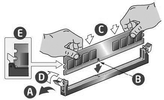
7. Press down on the memory module with your thumbs (letter C and B) while pulling up on the ejectors (letter A and D) with your index fingers to lock the module into the slot (letter E).
8. Ensure that all ejector tabs are in the upright locked position.
9. Replace the chassis cover.
10. Replace the power cords and peripherals.
11. Power on the appliance.
Replacing memory modules in 2U appliances
This section describes how to replace memory modules in the 2U appliances.
Figure: Memory module slot locations in GX and 2U appliances

Figure: GX DIMM locations

When adding new memory to the 2U appliances, add the memory in the blue slots first. Once the blue slots are full, populate the black slots. Use the lowest lettered/numbered slots first.
To replace memory modules in the 2U appliances
1. Power down the appliance.
2. Remove the chassis cover.
3. Remove the air duct.
4. Press the ejector tabs on the memory slots down and outward, and gently pull the memory module out of the slot.
5. Replace the memory module with an approved memory module of the same size.
Note: Replacing the existing memory module with a module of a different size causes the appliance to fail. You must use approved memory modules. Contact Riverbed Support at https://support.riverbed.com to obtain the correct memory modules.
6. Align the memory-module edge connector with the slot alignment keys and insert it into the slot.
The module slot has two alignment keys that allow you to install the module in only one direction.
Figure: Inserting the memory modules into the connector slot and securing
7. Press down on the memory module with your thumbs (letter C and B) while pulling up on the ejectors with your index fingers (letter A and D) to lock the module into the slot (letter E).
8. Ensure that all ejector tabs are in the upright locked position.
9. Replace the chassis cover.
10. Replace the power cords and peripherals.
11. Power on the appliance.
Replacing fans
This section describes how to identify fan status and replace fans in the 1U and 2U appliances. The section includes the following procedures:
You must power down appliances prior to replacing fans.
Determining fan status
This section describes how to determine the status of individual fans in the appliance.
To determine fan status on SteelHead
1. Connect to the CLI.
For details, see the Riverbed Command-Line Interface Reference Manual.
2. At the system prompt, enter the show stats fan command:
amnesiac> show stats fan
FanId RPM Min RPM Status
1 4508 1715 ok
2 4508 1715 ok
3 4508 1715 ok
4 4459 1715 ok
5 4557 1715 ok
On appliances where each fan has two rotors, each rotor has a unique status entry.
The output and number of fans vary depending on your appliance.
Note: Fan status isn’t available on NetShark.
Replacing fans in 1U appliances
This section describes how to replace fans in the 1U appliances. These appliances are equipped with four fans. The fans aren’t hot swappable; you must power down the appliance before replacing the fans.
Note: You must use approved fans. To order fans, contact Riverbed Support at https://support.riverbed.com.
To replace the fans in the 1U appliances
1. Power down the appliance.
2. Remove the chassis cover.
3. Identify the faulty fan.
The 1U appliance has four fans, in slots 2, 3, 4, and 5.
Figure: 1U fan numbers
4. Unplug the fan cable from the cable jack on the motherboard (number 1) and remove the faulty fan from the dock (number 2).
Figure: Fan cable jacks and removing fan unit

5. Insert the replacement fan into the dock (number 1) and plug the cables of the replacement fan unit into the cable jack (number 2).
Figure: Replacing a fan

6. Replace the chassis cover.
Note: If the RiOS IPMI alarm triggers when you open the chassis cover, enter the clear hardware error-log command in the CLI to clear the alarm. For details, see the Riverbed Command-Line Interface Reference Manual.
Replacing fans in 2U appliances
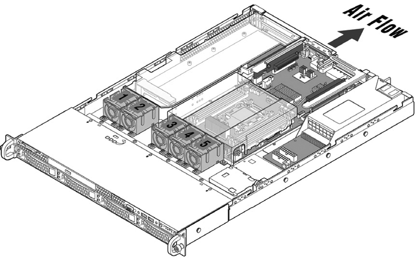
This section describes how to replace fans in the 2U appliances. The SteelHead GX10000 is equipped with six hot-swappable fans at the front of the chassis. The 2U CX, xx70, Interceptor 9600, and SteelFusion Core 3500 are equipped with five fans at the front of the chassis.
Important: You must use approved fans. To order fans, contact Riverbed Support at https://support.riverbed.com.
To replace the fans in the 2U appliances
1. Power down the appliance.
2. Remove the chassis cover.
3. Identify the faulty fan.
Depending on your appliance, there can be up to six fans. An LED on the fan indicates a failure.
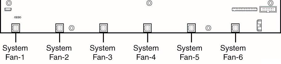
Figure: 2U fan layout with fan ID numbers
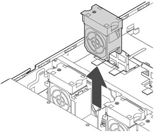
4. Pull the fan straight up to remove it.
Figure: Removing the fan in 2U appliances
5. Insert the replacement fan.
6. Replace the chassis cover.
7. Power on the appliance.
Note: If the IPMI alarm triggers when you open the chassis cover, enter the clear hardware error-log command in the CLI to clear the alarm. For details, see the Riverbed Command-Line Interface Reference Manual.