Overview
This document describes the cabling, initial configuration, licensing, and verification of Riverbed® SteelCentral™ AppResponse 11 on SteelCentral models 2180, 4180, and 8180, referred to collectively as xx80 models. It assumes that the product has already been mounted in a rack as described for SteelCentral model xx80 series products in the Riverbed Rack Installation Guide, available on the Riverbed Support web site.
When the installation is complete, your system is operating with a basic configuration. Configure it for normal operation on your network using the configuration instructions in the SteelCentral AppResponse 11 User’s Guide available on the Riverbed Support web site. Help is also available from the AppResponse 11 web user interface (UI).
Product Description
AppResponse 11 monitors network traffic seen on taps or on mirror (SPAN) ports of switches and routers while performing traffic analysis and high-speed packet capture. AppResponse 11 runs on SteelCentral appliances that can be ordered with various storage and interface options. The models, including storage unit (SU) options available for the SCAN-08180 base units, appear below.
Product Model | Rack Space | Length | Width | Height | Maximum Weight |
SCAN-02180 | 1U | 645 mm
(25.4 in.) | 436 mm
(17.2 in.) | 43.6mm
(1.72 in.) | 21 kg
(47 lbs) |
SCAN-04180 | 2U | 700 mm
(27.56 in.) | 440 mm
(17.32 in) | 87 mm
(3.43 in.) | 31 kg
(68 lbs) |
SCAN-08180 | 2U | 700 mm
(27.56 in.) | 440 mm
(17.32 in) | 87 mm
(3.43 in.) | 28 kg
(62 lbs) |
Safety Guidelines
Before you install, operate, or service the Riverbed product, you must be familiar with the safety information. Follow the safety precautions outlined in the Riverbed Safety and Compliance Guide when installing and setting up your equipment. Important: Failure to follow these safety guidelines can result in injury or damage to the equipment. Mishandling of the equipment voids all warranties. Please read and follow safety guidelines and installation instructions carefully.
Many countries require the safety information to be presented in their national languages. If this requirement applies to your country, consult the Safety and Compliance Guide.
Preparing For Installation
This section describes resources you need to have available before you install AppResponse 11 on an appliance. The next section describes how to cable and power on an appliance with AppResponse 11 software.
Data Sources
AppResponse 11 must be receiving traffic from at least one source in order for you to verify successful installation and configuration. The traffic source can be a tap or a mirror (SPAN) port on a switch or router.
Cable Connections
This section describes how to establish connectivity to your AppResponse appliance.
Access to the Network
If you lock down your network on a port-by-port basis, ensure that the following ports are open between the appliance and other devices it must communicate with:
◼ TCP/22 – (ssh) Command line interface
◼ TCP/443 – (https) Web interface and control from Riverbed SteelCentral Packet Analyzer Plus
◼ UDP/123 – (ntp) Time synchronization
◼ UDP/319 and 320 – (ptp) Time synchronization
Primary or Management Port
An xx80 chassis is equipped with a 1000base-T primary management port, PRI, used to connect to the management network. The primary management port is set for DHCP and auto-negotiation by default.
Ensure that:
◼ The management network has a switch port available for use by AppResponse 11.
◼ A straight-through cable to a switch port on the management network is available at the rack location.
◼ The management network switch port is set to establish a connection at 100 or 1000 Mb/s and full duplex. The xx80 appliances also support 10 Mb/s, as well as half duplex.
◼ A device with a compatible web browser is available on the management network for signing in to the AppResponse 11 web interface.
Auxiliary Port
An xx80 chassis is equipped with a secondary management port, named AUX, that is disabled by default. The AUX port is configurable, and is useful if you want to keep network data and network control traffic on separate networks.
PRI and AUX should not be enabled on the same subnet.
Ensure that:
◼ A straight-through cable to a switch port on the network is available at the rack location.
◼ The network switch port is set to establish a connection at 100 or 1000 Mb/s and full duplex.
Traffic Monitoring Interfaces
Ensure that the necessary taps or mirror ports are set up in your network and that the correct electrical or optical cables are available in the rack where the AppResponse 11 appliance is to be installed.
The interfaces that capture network traffic are provided by network interface cards (NICs). These may be optical or copper, depending on your ordered configuration. Check your purchase documentation, or view the back panel of the chassis to determine the number and type of cables needed.
Network add-on cards | Size (*) | Manufacturing part # | Orderable part # |
Four-Port 1-GbE Fiber SFP | HHHL | 410-00124-01 | NIC-1-001G-4SFP |
Four-Port 1-GbE Copper Base-T | HHHL | 410-00116-01 | NIC-1-001G-4TX |
Two-Port 10-GbE Fiber SFP+ | HHHL | 410-00036-02 | NIC-1-010G-2SFPP |
Four-Port 10-GbE Fiber SFP+ | HHHL | 410-00108-01 | NIC-1-010G-4SFPP |
Two-Port 40-GbE Time Stamp (supported on 8180 only) | FHHL | 410-00214-01 | NIC-1-040G-2QSFP-TS |
Two-Port 100-GbE QSPF+ Time Stamp (supported on 8180 only) | FHFL | 410-00239-01 | NIC-1-100G-2QSFP-TS |
*HHHL = Half Height, Half Length; FHHL = Full Height, Half Length; FHFL = Full Height, Full Length. |
SFP | Manufacturing part # | Orderable part # |
SFP 1-GbE SX | 410-00139-01 | TRC-1-SFP-SX |
SFP 1-GbE LX | 410-00140-01 | TRC-1-SFP-LX |
SFP+ 10-GbE DAC | 410-00142-01 | TRC-1-SFPP-DAC |
SFP+ 10-GbE SR | 410-00143-01 | TRC-1-SFPP-SR |
SFP+ 10-GbE LR | 410-00144-01 | TRC-1-SFPP-LR |
QSFP+ 40-GbE SR | 410-00147-01 | TRC-1-QSFP-SR4 |
QSFP+ 40-GbE LR | 410-00148-01 | TRC-1-QSFP-LR4 |
QSFP+ 100-GbE SR4 | 410-00242-01 | TRC-1-QSFP28-SR4 |
QSFP+ 100-GbE LR4 | 410-00243-01 | TRC-1-QSFP28-LR4 |
Console Port
The console port is a DB9 port. By default, the AppResponse 11 installation process uses a 9600 baud rate. A cable with a DB9 connector, such as the cable supplied in the accessory kit, is used to connect. See “Console Cable Wiring” for the pinouts of the supplied RJ45 to 9-pin D-subminiature cable.
Ensure that a terminal server or a device running a terminal emulation program such as HyperTerminal or Tera Term Pro is available.
Storage Units
You can connect Storage Units to an 8180 base unit, either SCAN-SU-4 (48TB) or SCAN-SU-10 (120TB). When using more than one Storage Unit, all Storage Units must be the same model.
Power
All SteelCentral model xx80 series products have two power supplies, including the storage units. Riverbed recommends that the power supplies use two different circuits, if they are available. Use the power cables supplied in the accessory kit. All models power on automatically when connected to power and after a power outage.
Cabling and Powering On
Before plugging in the power supplies, make the connections as described below.
Management Network Connections
You can operate and manage the appliance over the management network after the appliance is powered on. Connect a cable from the management network to the RJ45 connector labeled PRI.
If you enable AUX, the secondary management port, it must not be on the same subnet as the primary management port (PRI).
Traffic Monitoring Interface Connections
Connect the cables from the live traffic sources to the interface connectors (mon2_0, mon2_1…) on the back of the chassis. Interface names are monS_N where “S” is the slot where the NIC is installed and “N” is the interface number (0-3), left to right. Note that:
◼ Slot numbers begin with 2 (NICs are not supported in slot 1) and interface numbers begin with 0.
◼ Replacing a NIC with the same model retains the interface name and settings.
◼ Replacing a NIC with a different model retains the interface name, but the auto-negotiation and deduplication settings are lost, and must be respecified.
◼ Old interfaces will show as missing if there isn’t a new one to map it to (for example, if a 4 port card is replaced with a 2 port card). The description is preserved when a different model NIC is installed and there is a new port to map to the old one.
Optical Connectors
Use only Riverbed branded SFPs.
Models that include a 1-Gb/s optical network interface card have SFP transceiver inserts pre-installed. If you ordered an SX model, use a multimode fiber-optic cable with an LC connector. If you ordered an LX model, use a single-mode fiber-optic cable with an LC connector.
Models that include a 10-Gb/s network interface card have SFP+ transceiver inserts pre-installed. If you ordered an SR model, use a multimode fiber-optic cable with an LC connector. If you ordered an LR model, use a single-mode fiber-optic cable with an LC connector.
A 40-Gb/s or 100-Gb/s optical network interface card uses QSFP+ transceiver inserts.
Console Connection
If there is to be a permanent connection from the console port to a terminal server, make the connections now. Refer to “Console Cable Wiring” for console port pin assignments. The console port can be used for software installation if the serial install option is passed.
If you will temporarily connect to the console for configuring the software, ensure that you have a:
◼ Laptop or other device running a terminal emulation program such as HyperTerminal or Tera Term Pro. Set the device’s terminal emulator to 9600 Baud, 8 data bits, 1 stop bit, no parity bit, vt100 emulation, and no flow control.
◼ Cable with a 9-pin D-subminiature connector. The accessory kit includes a DB9 to DB9 cable.
◼ Alternatively, a KVM device can be used to connect to the console port (see below).
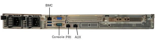
2180 Rear Panel
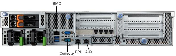
4180/8180 Rear Panel
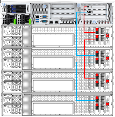
Connecting Storage Units to an 8180
Use the supplied external mini-SAS HD cable with SFF-8644 connectors to connect the base unit and the first Storage Unit. Follow the instructions below.
Slot 4 and slot 5 on the 8180 chassis each includes two SFF-8644 SAS ports, labeled “A” and “B” in the connection illustration below. On each of those slots, port A is used to connect additional Storage Units, and port B is not used. Additional Storage Units are connected to the 8180 in a manner that is load-balanced and daisy-chained:
1. Connect the first Storage Unit to port A on slot 4.
2. Connect the second Storage Unit to port A on slot 5.
3. If you are using a third Storage Unit, connect it to port B on the first Storage Unit (not port B on the 8180’s slot 4).
4. If you are using a fourth Storage Unit, connect it to port B on the second Storage Unit (not port B on the 8180’s slot 5).
5. For any additional Storage Units, continue this pattern of daisy-chaining them in a load-balanced fashion. You can have a maximum of eight Storage Units daisy-chained from port A on slot 4, and the same number daisy-chained from port A on slot 5, for a total of 16 Storage Units.
The illustration that follows shows a simple example with a total of four additional Storage Units. Note the manner in which the Storage Units are load-balanced, and note as well that port B on the 8180 unit is not used.
Review “Powering on an AppResponse 11 appliance” before you plug in your AppResponse 11 model. All models have two power supplies. Plug each power supply into a different circuit, if available, using the supplied power cords.
Powering on an AppResponse 11 Appliance
Read the instructions below before powering on your AppResponse 11 appliance.
Important: The installation of SCAN-08180 appliances with Storage Units requires that the Storage Units are connected and powered on before the appliance is powered on.
Powering on a SCAN-08180
An enrollment process must link each Storage Unit to an 8180 base unit before it can be used for storage. When a base unit performs an enrollment, any existing data is lost and the storage unit is formatted as RAID 0 by default. For more information on AppResponse 11 storage units, see the section on configuring and managing Storage Units in the SteelCentral AppResponse 11 User’s Guide, version 11.6.5 and later.
To initialize the Storage Units:
2. Make sure all Storage Units connected to the 8180 are the same model, either 48TB or 120TB.
3. Connect the Storage Units to power before the 8180.
4. Check that each Storage Unit’s status indicator, the power button on the left ear at the front of each storage unit, is lit green. If the power button LED is not lit, check the power connection to the Storage Unit.
5. Once all the Storage Units are connected and powered on, confirm that they are connected to the 8180, then power on the base unit.
6. When a new 8180 is connected to power it detects the storage units. As of Version 11.9.0, AppResponse 11 does not initialize Storage Units automatically; you must initialize them manually after installation. For new AppResponse 11 installations, this is handled by the setup wizard, which prompts you to initialize the Storage Units and specify their RAID mode and encryption. After installation of a new AppResponse 11 system, the CLI command storage reinitialize can be used to initialize and configure multiple Storage Units in the same manner as the wizard. Note that, when a new Storage Unit is attached at a later time, it will be detected automatically. Storage is initialized as RAID 0 by default.
Once the base unit has powered on and all Storage Units are initialized, you are ready to perform a basic AppResponse 11 configuration.
Preparing to Install AppResponse Software On a SCAN-xx80 Appliance
AppResponse can be installed on the following SteelCentral appliances:
◼ SCAN-02180
◼ SCAN-04180
◼ SCAN-08180
The installed application is overwritten and all storage is lost on an appliance. There is no means to recover either the application or the storage.
To install AppResponse 11 software, the AppResponse 11 appliance BIOS needs to boot from an external USB key. Without an external USB key inserted, the appliance will boot from its internal disks any time it loses power or is power-cycled. To install new software, Riverbed recommends that you use the BIOS configuration tool to specify the USB key in the Save & Exit menu's Boot Override list. This will enable you to boot the appliance from the USB key without changing the HDD boot settings that will be used during ordinary reboots.
1. Use a web browser to navigate to the Riverbed Support site to select the appropriate software version and download the Install (ISO): https://support.riverbed.com/content/support/software/steelcentral-npm/appresponse-ar11.html
2. Create a bootable USB key. Load the AppResponse 11 software onto the USB key using the Linux "dd" command to write the ISO directly to the USB, or use a universal USB installer tool such as Etcher [https://www.balena.io/etcher/].
3. Connect to the AppResponse11 appliance using a keyboard and monitor.
4. Insert the bootable USB key into the AppResponse appliance. Insert the USB key into any USB connector on the front of the appliance.
5. Switch on or power-cycle the appliance. The power switch is located in the upper right corner of the front of the appliance.
6. During the power-on self-test (POST) sequence, press F2 to start the BIOS configuration tool. To install the AppResponse 11 software, the BIOS needs to boot from the external USB key.
7. In the BIOS configuration tool, go to the Save & Exit menu. Navigate to the USB key in the Boot Override list, then press Enter to select it.
8. Type “F4” to save the change and exit the BIOS configuration tool.
9. When the system finishes booting from your USB key, enter “install” at the “boot:” prompt. The software installation takes approximately 20 minutes.
10. When the software installation is complete and the “boot:” prompt is displayed, remove the USB key and power-cycle the appliance. After the system reboots, the login prompt appears.
11. Run the configuration wizard, as described in the section,
Configuration, that follows. Log in using “admin” user name and password.
12. Enter the required information when prompted. The system reboots when you exit the configuration wizard. Wait until the system completes rebooting before you continue to the next step.
13. Log in to the web user interface using the “admin” user name and password.
Configuration
After AppResponse 11 finishes booting, a log in prompt appears on the console terminal. Perform the initial AppResponse 11 configuration using the AppResponse 11 CLI, as described below, or using the Web UI.
Initial Setup
1. Using the console port and a terminal emulator, log in to the AppResponse 11 command line interface (CLI) using the default sign in name and password.
Log in as: admin
host’s password:admin
Last login: Thu Feb 28 15:02:52 2019 from 10.18.41.255
host >
2. Access the setup wizard in the CLI. Type enable at the command prompt, followed by configure terminal to start the configuration terminal. Type wizard to initiate the setup wizard.
a. Type ? for a list of available CLI commands.
b. Use the Tab key to show the next entries on a command line.
c. Use the Tab key to auto-complete a CLI command.
3. The wizard is used to configure the appliance’s base interfaces to connect to your management network. Once established, the AppResponse 11 web user interface (web UI) is used to complete the configuration, manage users, and monitor network traffic.
The wizard prompts include default settings shown in [brackets]. Press Enter to use the default and continue to the next setting.
Note: The CLI asks for settings only where needed, so CLI sessions may differ from session to session.
Here is an example of the output:
Hostname [localhost]: appresponse11
Primary interface DHCP enabled [yes]:
Aux interface enabled [no]:
Timezone (enter * to list) [America/Los_Angeles]:
4. When you have completed the settings, the following summary appears:
You have entered the following configuration:
1: Hostname: appresponse11
2: Primary interface DHCP enabled: yes
3: Aux interface enabled: no
4: Timezone (enter * to list): America/Los_Angeles
To change an answer, enter the step number to return to it
5. When you have finished the configuration, enter exit to all CLI prompts until the SSH session end.
host (config) # exit
6. If you cannot open the web UI, rerun the wizard to revise the settings as needed.
The wizard configures the IP management network. The bullets below contain specific information for each setting:
◼ The hostname (without the domain) accepts lowercase alphanumeric characters, hyphens, and periods, but no spaces.
◼ Enter yes to use DHCP for the primary management port or no to use a static IP configuration, and press Enter. When setting up an address to be provisioned by DHCP, use the MAC address of the management port (PRI or AUX) on the label on top of the appliance.
◼ For a static IP configuration, specify the IP address, the IP net mask, and the default gateway.
◼ You choose whether to use the second management port (AUX). Enter yes to enable aux. If aux is enabled, configure aux for either DHCP or a static IP configuration.
◼ Configure the DNS servers (as a comma- or space-separated list) and the domain name of the appliance. Note: If DHCP is used for the primary management network configuration, these steps are skipped (because they are configured by the DHCP server).
◼ Set the time zone of the appliance. Entering an asterisk (*) lists the available time zone areas. To specify a particular time zone, enter the full time zone including the area (for example, Europe/Rome).
◼ SSH, NTP, and PTP are configured under Administration in the AppResponse 11 menu bar in the web UI.
If you have used DHCP to provision an IP address for AppResponse 11, at the console prompt enter interface show primary to find the IP address of the primary management port.
host (config) # show interfaces primary
Interface primary state:
Up: yes
Interface type: Ethernet
DHCP enabled: yes
IP address: 10.33.159.73
Netmask: 255.255.255.0
DHCPv6 enabled: no
Link-local address: ffff::250:56ff:fe88:a672/64
Speed: 10000 Mbit/Sec
Duplex: full
MTU: 1500
HW address: 00:50:56:ff:a6:72
Link: yes
Ensure that you can ping this address from another workstation on the management network before logging out of the command line interface.
Configuring and Managing Storage Units
The AppResponse 11 8180 base unit (SCAN-08180) has no internal storage. You can connect Storage Units of the same model, either SCAN-SU-4 or SCAN-SU-10, to a base unit. Up to sixteen external Storage Units can be connected to an 8180 base unit for storage.
◼ When a new base unit is connected to power it detects the storage units. As of Version 11.9.0, AppResponse 11 does not initialize Storage Units automatically; you must initialize them manually after installation. For new AppResponse 11 installations, this is handled by the setup wizard, which prompts you to initialize the Storage Units and specify their RAID mode and encryption. After installation of a new AppResponse 11 system, the CLI command storage reinitialize can be used to initialize and configure multiple Storage Units in the same manner as the wizard. Note that, when a new Storage Unit is attached at a later time, it will be detected automatically. Storage is initialized as RAID 0 by default.
◼ Initialization is done at the Storage Unit level, that is, an uninitialized Storage Unit is initialized whenever the base unit boots.
◼ Initialization fails
◼ if an invalid Storage Unit is detected
◼ if a disk fails
◼ If an incompatible disk is found
◼ The initialization process formats storage as RAID 0 storage by default. After initialization, storage can be reinitialized as RAID 5 or RAID 6 for storage redundancy, using the AppResponse 11 CLI.
◼ If a Storage Unit fails or is removed, storage may continue to function but with a limited capacity. If all Storage Units fail or are removed, storage will not function.
◼ Reinitializing a Storage Unit destroys all data on that single Storage Unit. All other Storage Units are unaffected. Packet data and corresponding analysis will be affected accordingly.
AppResponse 11 CLI Storage and Service Commands
Storage Unit configuration and management is done using the AppResponse 11 command line interface.
Storage Unit Status
◼ show storage units—displays Storage Unit status and details
◼ show storage unit <name>—displays Storage Unit <name> status and details
Storage Data Section Status
◼ show storage data_sections—displays storage data sections status and details
◼ show storage data_section <name>—displays storage data section <name> status and details
Storage Data Area Status
◼ show storage data_areas—displays storage data areas status and details
◼ show storage data_areas section <name>—displays status and details of data areas on a data section
◼ show storage data_area <name>—displays storage data area <name> status and details
◼ show storage data_area <name> section <name>—displays status and details of the data area belonging to the named data module on a given data section if one exists
Storage Data Module Status
◼ show storage data_modules—displays storage data modules status and details
◼ show storage data_module <name>—displays storage data module <name> status and details
Storage Data Section Reinitialization
◼ storage data_section <name> reinitialize—reinitializes data section <name> using the default RAID0 mode
Storage Data Section Mode Change
◼ storage data_section <name> reinitialize mode <raid0|raid5|raid6>—Changes the RAID mode used by the data section <name>
Initializing Storage Units
When a base unit boots, it detects connected and powered up Storage Units. Each Storage Unit’s identity is stored by the base unit and the Storage Unit is formatted as RAID 0 storage by default.
If other Storage Units are connected and powered on after a base unit boots, they will be detected and displayed without needing to reboot base unit. After a reboot, the Storage Units will have their "Status:" as "active” and "In Use:” is “yes" indicating that packet storage is configured on the storage unit.
Changing the Storage RAID Level
Storage can be reinitialized to RAID 0, RAID 5, or RAID 6 using the AppResponse 11 CLI. When changing the format of storage all existing packet data is lost.
For example, to change the storage RAID level on storage unit LDABC12345678 follow the steps below.
1. Using a terminal emulator such as PuTTY or Tera Term, SSH to the AppResponse 11 CLI.
2. Enter no storage data_area packet_capture section <primary_capture_data> to remove existing data before reinitializing:
no storage data_area packet_capture section LDABC12345678
3. Enter:
storage data_section reinitialize LDABC12345678 mode <RAID0|RAID5|RAID6>
storage is available within seconds, but the storage status will be rebuilding until it is completed. When the storage is reinitialized in RAID 5 or RAID 6, the rebuild process starts after a few minutes. If changing the storage to RAID 0, it is available immediately.
4. Enter:
storage data_area packet_capture section LDABC12345678
5. Once completed, you can use the following command to check the storage unit mode:
show storage
Optional Customizable Storage
For many models of AppResponse 11 appliance, you have the option of configuring the system with reduced packet storage space in order to store more analysis data. Two modes are supported:
◼ Packet data priority mode (pktprio) is the default, and is similar to the configuration of the earlier NetShark platform, maximizing packet storage and using a smaller retention time for other data.
◼ Metric priority mode (metprio) is similar to the configuration of the earlier AppResponse 9 platform, increasing the retention time of analysis modules including aggregates, probe, WTA, DB performance and VoIP, but reducing the packet storage accordingly.
In each mode, the general behavior of the system is the same, but the location where packet and analysis data is stored changes, and the amount of space allocated for each type of analysis data and for packet data varies. If you have a lot of existing analysis data, the transition from pktprio to metprio could take a long time. The layout configuration process should preserve all analysis data, except that packet capture data on the destination data section will be lost.
The transition of storage mode from pktprio to metprio is one-way and irreversible.
Changing the RAID mode of a Storage Unit must be done prior to applying "metprio" mode. Before making any changes to the storage mode, you should evaluate any changes you may wish to make to the default RAID 0 setup on your packet storage units. Any RAID changes must be made before changing the storage mode. If you happen to do this in reverse order, you will need to perform a reinstall or do a factory reset from the web UI.
During the time the change from pktprio to metprio is in progress, you may see error messages displayed in the Web UI as a result of some background services stopping.
The configuration process is invoked via a CLI command, takes up to a few hours to run, and is followed by a mandatory reboot. After the reboot, various analysis components use the packet capture volume to store data, increasing their retention times. It is not possible to switch back to the original (default) mode. In order to change the storage mode (or to specify a different storage unit for metprio mode), either a factory reset or a full reinstallation is required, and the storage that was configured previously for metprio mode must be reinitialized.
Supported CLI commands
The following CLI commands are provided to support this feature:
◼ show storage layout—Display information about the current mode and the status of any operations.
◼ show storage layouts—Display a list of all available modes and valid data sections.
◼ storage layout metprio [data_section <data section>]—Change the storage layout mode to metprio.
Changing the storage mode
To change from packet data priority mode (pktprio) to metric priority mode (metprio):
1. Log in to he CLI as admin
2. Execute: enable
3. Execute: configure terminal
4. Execute: show storage layout and verify that the current layout is “pktprio”.
5. Execute: show storage layouts and verify that the “metprio” layout is available with a valid data section. The valid data section should be:
◼ primary_capture_data for 2180 and 4280 models.
◼ storage device name(s) for SU systems (e.g., LDABC12345678)
6. Execute the command to reconfigure the storage layout.
◼ For 2180/4180 systems: storage layout metprio data_section primary_capture_data
◼ For 8180 systems: storage layout metprio data_section <storage_device_name>
7. Respond yes to the prompt to initiate the layout reconfiguration.
8. The layout reconfiguration progress is reported on the CLI:
Reconfiguring to layout 'metprio' ... xx% ... yy%.
The duration of the layout reconfiguration depends upon the amount of analysis data that needs to be transferred. The layout reconfiguration is complete when the final status that is reported on the CLI shows Done and you are prompted to reboot on the CLI and the Web UI.
9. Respond yes to the CLI reboot prompt or reboot from the Web UI.
10. After the reboot, the system is in metric priority mode. You can confirm this by executing show storage layout in the CLI. The current layout now should be “metprio”.
Opening the AppResponse 11 Web UI
Once AppResponse 11 can be pinged from the console, you can use a browser to open the AppResponse 11 web UI. The AppResponse 11 web UI is tested using Internet Explorer, Chrome, and Firefox. Other browsers might not be compatible. Make sure that SSL, cookies, and JavaScript are enabled in your browser.
1. Point a browser to https://<AppResponse 11> where <AppResponse 11> is the IP address or DNS name of AppResponse 11. This displays the web UI sign in page.
2. Sign in using the default web interface username and password.
Username: admin
Password: admin
The username and password can be changed on the Settings > Users and Groups page of the web interface.
Licensing
An AppResponse appliance requires a license to collect and analyze network traffic. When you purchase an AppResponse appliance or an upgrade, Riverbed sends an email to your Support account Username containing the appliance serial number. The serial number is used to install the Feature Keys that:
◼ Allow the AppResponse 11 appliance to operate.
◼ Enable the licensed capabilities and capacities, for example, a Web Transaction Analysis add-on module.
Important: When AppResponse 11 is installed on an appliance, the license is for that appliance serial number and can only be used on that appliance. The license cannot be moved to another appliance.
The serial number can be used on the Licenses page of the Riverbed Support site (https://licensing.riverbed.com) to view and manage your licenses. For more information on licenses, see Licensing in the AppResponse 11 User’s Guide or the AppResponse 11 web UI Help.
Licensing an AppResponse 11 Appliance with an Internet Connection
By default, AppResponse automatically opens a connection over the Internet to the Riverbed Licensing web site and validates the license. The license is then activated and the license’s Feature Keys are automatically installed. No further action is required.
Licensing an AppResponse 11 Appliance with No Internet Connection
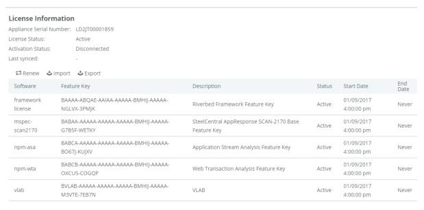
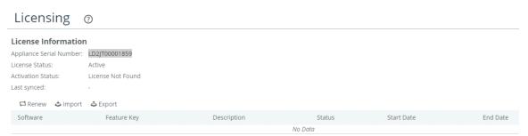
1. In the AppResponse 11 web UI go to Administration > Other: Licensing.
2. The appliance serial number is displayed but no Feature Keys are installed. AppResponse is not operating. The default Insight on the Home page of the AppResponse 11 web UI has no data.
3. On a computer with an Internet connection, go to the Licenses page of the Riverbed Support site (https://licensing.riverbed.com) and enter the appliance serial number. The Feature Keys are displayed. These Feature Keys are to be imported into the AppResponse 11 appliance.
4. Return to Administration > Other: Licensing page in the AppResponse 11 web UI.
5. In the toolbar above the Feature Key table click Import to open the Import Feature Keys screen.
6. Copy the Feature Keys from the Licenses page into the Feature Key text box. The first Feature Key must be the CLMF-FRAMEWORK key; additional keys can then follow in any order, one per line.
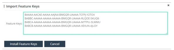
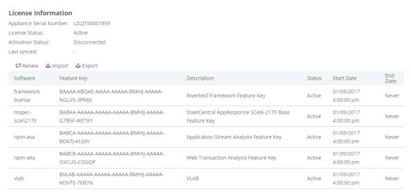
7. Click Install Feature Keys to finish the license install.
Installation Verification
Once AppResponse 11 has been licensed, use the AppResponse 11 web UI to verify that the appliance has been successfully installed.
Confirming basic configuration
1. Point a browser to https://<AppResponse 11> where <AppResponse 11> is the IP address or DNS name of the AppResponse 11 appliance. Sign in using the default web UI username and password.
Username: admin
Password: admin
This displays the AppResponse 11 web UI Home page by default.
A capture job using a Virtual Interface Group (VIfG) made up of all the appliance monitoring interfaces starts automatically when the appliance boots. Also, a Summary: All Traffic Insight is displayed on the web UI Home page. Your appliance should display current traffic metrics in charts and tables as shown above. If not, there may be a connectivity problem or an interface issue.
2. From the AppResponse 11 menu bar go to Administration > System Settings: Capture Jobs/Interfaces, Monitoring Interfaces tab to check the link status, speed, and bytes and packets received for each monitoring interface you have connected.
3. If a monitoring interface Name appears as mon0_N, the NIC is installed in an incorrect slot.
4. Link Status should be UP for all connected interfaces. If DOWN, check the connection and the traffic source.
5. Received bytes and packets for all connected monitoring interfaces should be increasing as traffic is received. Refresh the browser page (or wait for it to auto-refresh) and confirm that the received packet counts are incrementing.
6. After you have verified that all connected interfaces that you have connected to network traffic sources are up and that the received bytes and packets counters are incrementing, the configuration is complete.
7. Use the AppResponse 11 CLI to view the status of data sections and storage units using the command show storage data_sections.
8. Confirm that packet capture data is being saved. You should see a primary_capture_data data section with a storage unit identifier such as LDXYZ12345678 with Status: active.
Troubleshooting Storage Units
Solutions to some common storage installation problems are provided below.
Problem: Storage Failed
This can occur if:
◼ An invalid Storage Unit was found. No initialization occurred.
◼ A Storage Unit has a failed disk.
◼ A Storage Unit has a disk that is not supported.
Solution: An invalid Storage Unit was found
1. Identify the INVALID storage unit.
2. To create storage choose “a” or “b” below.
a. It is recommended that you replace the INVALID storage unit(s) before creating storage. If you disconnect the defective or mismatched storage unit and build package storage without it (option “b”) a reinitialization is required to add a replacement unit later and any existing packet capture data is lost.
i. Connect and power on the replacement storage unit.
ii. Reboot the base unit.
b. Disconnect the invalid or mismatched unit.
i. Power off and disconnect the unit from the base unit configuration. A storage unit cannot be disconnected through software.
ii. Reboot the base unit. Important: Should you later decide to add a replacement storage unit reinitialization is required and any existing packet capture data is lost.
Solution: A storage unit has a failed disk
To resolve:
1. The amber Fault LED is lit indicating a failed drive.
2. Replace all failed disks.
3. Reboot the base unit.
Solution: A storage unit has a disk that is not supported
To resolve:
1. An unsupported disk has been detected. Examine each disk and identify any disk(s) that are not supported by Riverbed.
2. Replace all unsupported disks.
3. Reboot the base unit.
4. Contact Riverbed if you have questions about an unsupported disk.
Problem: Storage is smaller than expected
Use the AppResponse 11 CLI to check the size of storage, as follows:
host > show storage data_module packet_capture
Data module packet_capture
Requires role: capture
Data Areas:
Data Section: LD99999
Quota (MB): 68664401
Status: active
Data Section: LD9YQ00175ABC
Quota (MB): 68664401
Status: active
Total quota (MB): 137328802
Total used (MB): 137327616
host >
Compare the number of storage units listed with the number of storage units to be deployed. This list is by storage unit serial number, not the order that the storage units are connected to the base unit. Confirm that the storage size matches the number of storage units deployed.
An incorrect storage size can occur if:
◼ A storage unit was not connected or not powered on when a reinitialization occurred.
◼ A storage unit was added but not reinitialized.
◼ There is a mix of 4 TB and 6 TB disks used in the storage unit.
Solution:
A storage unit was not connected or not powered on when a reinitialization occurred.
1. When multiple storage units are deployed in a linear daisy chain, a storage unit that is not connected or not powered on, and all storage units following it, are not initialized by the base unit. On an 8180, check the storage units in each linear daisy chain.
2. Starting with the missing storage unit that is closest to the base unit in the linear daisy chain, find the storage unit that is not connected or not powered on. As necessary reconnect and power on the storage unit.
a. As necessary, reconnect and power on all subsequent storage units in the linear daisy chain.
b. The missing storage unit(s) must be reinitialized to add them to storage. Any existing storage data is lost.
3. Reboot the base unit. Any existing storage data is lost.
A storage unit was added after an initialization occurred.
1. Run this CLI command:
host > (config) # show storage units
Storage unit LD99999
Data section LD99999
Mode: RAID0
Supported Modes: RAID0, RAID1, RAID5, RAID6
Roles: capture, data
Status: active
In Use: yes
Total size (MB): 68664401
Unreserved (MB): 0
Data Areas:
packet_capture:
Quota (MB): 68664401
Used (MB): 68663808
Total allocated (MB): 68664401
Total used (MB): 68663808
Storage unit LD9YQ00175ABC
Data section LD9YQ00175ABC
Mode: RAID0
Supported Modes: RAID0, RAID1, RAID5, RAID6
Roles: capture, data
Status: active
In Use: yes
Total size (MB): 68664401
Unreserved (MB): 0
Data Areas:
packet_capture:
Quota (MB): 68664401
Used (MB): 68663808
Total allocated (MB): 68664401
Total used (MB): 68663808
host > (config) #
2. Check the output to see if one or more storage units are missing and that all other storage units have a status of active and are in use. The missing storage unit(s) is connected to the base unit and powered on but has not been initialized and is not a part of storage.
3. Reboot the base unit. Any existing storage data is lost.
There is a mix of 4 TB and 10 TB disks used in the storage unit.
1. Replace the disks as necessary.
2. Reboot the base unit. Any existing storage data is lost.
Changing the Default Password
When installation is finished, you can change the default password using the AppResponse 11 web user interface.
1. Go to Administration > Account Management: User Administration.
2. Select the admin user in the table.
3. Click the pencil (edit) icon that pops up at the end of the row.
4. Check the Change Password box.
5. Enter the old password and the new password.
6. Click Apply when finished or Revert to cancel the change.
7. Record your new password in a safe place.
If lost, this password cannot be recovered by Riverbed.
Additional Configuration
To complete the configuration of AppResponse 11 for traffic monitoring, including setting up interfaces, capture jobs, host groups and policies, refer to the AppResponse 11 User’s Guide or the online Help available from the AppResponse 11 menu bar.
Contacting Riverbed
Options for contacting Riverbed include:
◼ Internet - Find out about Riverbed products at http://www.riverbed.com.
◼ Support - If you have problems installing, using, or replacing Riverbed products, contact Riverbed Technical Support or your channel partner who provides support. To contact Riverbed Technical Support, please open a trouble ticket at https://support.riverbed.com or call 1-888-RVBD-TAC (1-888-782-3822) in the United States and Canada or +1 415 247 7381 outside the United States.
◼ Professional Services - Riverbed has a staff of engineers who can help you with installation, provisioning, network redesign, project management, custom designs, consolidation project design, and custom-coded solutions. To contact Riverbed Professional Services, go to http://www.riverbed.com or email proserve@riverbed.com.
◼ Documentation - Riverbed continually strives to improve the quality and usability of its documentation. We appreciate any suggestions you may have about our on line documentation or printed materials. Send documentation comments to techpubs@riverbed.com.
Specifications
This section cites important operation information for the xx80 models.
Power
Line voltage: 2180: AC 100-240V/9A; 4180/8180: AC 100-127V/10A, AC 200-240V/5A
Line Frequency: 50 - 60 Hz
Power (Typical)
The xx80 models require the following power per model:
SCAN-02180: 132W
SCAN-04180: 308W
SCAN-08180: 408W
SCAN-SU-4: 150W
SCAN-SU-10: 170W
BTU
The xx80 models typically dissipate heat in the following amounts:
◼ SCAN-02180: 450 BTU/hr
◼ SCAN-04180: 1050 BTU/hr
◼ SCAN-08180: 1391 BTU/hr
◼ SCAN-SU-4: 512 BTU/hr
◼ SCAN-SU-10: 580 BTU/hr
Cooling
Ambient air for the xx80 models should be:
◼ Air temperature: 10° C ~ 35° C (50° F to 95° F)
◼ Relative humidity: up to 90%, non-condensing at 35° C
Operating altitude up to 10,000 feet