Installing NICs for SteelHead Virtual Edition Appliances
This chapter describes how to install NICs for SteelHead Virtual Edition (SteelHead‑v) appliances. It includes these sections:
This chapter assumes you have installed and configured the SteelHead-v appliance. For details, see the SteelHead (Virtual Edition) Installation Guide.
The NICs for the SteelHead-v hardware support fail-to-block mode. For more information, see
Chapter: Fail-to-Block Mode.Before you begin
To successfully install a NIC in an ESXi host for SteelHead-v, you need the following:
• 64-bit ESXi host with a PCIe slot.
• vSphere Client access to the ESXi host.
• VMware ESXi 5.0 or later and RiOS 8.0.3 or later.
The number of hardware bypass pairs (that is, one LAN and one WAN port) supported is determined by the model of the SteelHead-v:
• Models V150, V250, and V550: one bypass pair
• Models V1050 and V2050: two bypass pairs (that is, two LAN and two WAN ports)
• Models VCX555, VCX755, VCX1555, VCX 5055, and VCX 7055: two bypass pairs
• Models VCX10 through VCX110: two bypass pairs
You can install a four-port card in an ESXi host for a SteelHead-v150, 250, or 550. However, only one port pair is available because the SteelHead-v model type determines the number of pairs.
These configurations have been tested:
• Two SteelHead-v guests, each using one physical pair on a single four-port Riverbed NIC
• Two SteelHead-v guests connecting to separate cards
• One SteelHead-v guest connecting to bypass pairs on different NICs
Make sure you follow proper ESD procedures when you handle the NIC:
• Wear properly grounded ESD straps.
• If an ESD strap isn’t available, touch a properly grounded metallic surface prior to handling the NIC.
• Don’t touch the electronic components on the NIC.
Supported NICs for SteelHead-v
This section describes the software requirements and NIC cards that support SteelHead-v.
All the NICs for SteelHead-v support fail-to-block mode. For more information, see
Chapter: Fail-to-Block Mode.For details on configuring VMware ESXi and NIC requirements for SteelHead-v, see the SteelHead (Virtual Edition) Installation Guide.
Software compatibility
SteelHead-v NICs have the following software requirements:
• SteelHead-v xx50 appliances require RiOS 7.0.2 or later.
• SteelHead-v CX555, CX755, and CX1555 appliances require RiOS 8.0 or later.
• SteelHead-v CX5055 and CX7055 appliances require RiOS 8.6 or later.
• VMware ESXi 5.0 requires RiOS 8.0.3 or later.
• Microsoft Hyper-V requires RiOS 9.7 or later.
• Kernel-based Virtual Machine (KVM) requires RiOS 9.2 or later.
Supported cards
The following table summarizes the NICs compatible with SteelHead-v appliance.You can install a four-port card in an ESXi host for a SteelHead-v 150, 250, or 550; however, only one port pair will be available because the SteelHead-v model type determines the number of pairs.
NICs for SteelHead (virtual edition) | Manufacturing part # | Orderable part # | Virtual appliances |
Two-Port TX Copper GbE card | 410-00043-01 | NIC-001-2TX | 150, 250, 550, 555 |
Four-Port TX Copper GbE card | 410-00044-01 | NIC-002-4TX | 555, 755, 1555, 5055, 7055 |
Two-Port SR Multimode Fiber 10 GbE card (second generation) | 410-00302-02 | NIC-008-2SR | 5055, 7055 |
The following cards are supported on SteelHead-v VCX10 through VCX110running ESXi/ESX, Hyper-V or KVM:
Riverbed NICs for SteelHead-v | Manufacturing Part # | Orderable part # |
Four-Port 1-GbE Copper Base-T | 410-00115-01 | NIC-1-001G-4TX-BP |
Four-Port 1-GbE Fiber SX | 410-00122-01 | NIC-1-001G-4SX-BP |
You must use Riverbed NICs for fail-to-wire or fail-to-block with SteelHead-v. NIC cards without a bypass feature from other vendors are supported for functionality other than fail-to-wire and fail-to-block, if supported by the hypervisor.
Identifying interface names in SteelHead-v
The interface names for the NICs in the SteelHead Management Console and the CLI are a combination of the slot number and the port pairs (lan<slot>_<pair>, wan<slot>_<pair>). For example, if a four-port NIC is located in slot 0 of your appliance, the interface names are lan0_0, wan0_0, lan0_1, and wan0_1 respectively.
The SteelHead-v model determines the maximum number of hardware bypass pairs.
V150, V250, and V550 appliances support one bypass pair (one LAN and one WAN port).
VCX555, VCX755, VCX1555, VCX5055, and VCX7055 appliances support two bypass pairs (two LAN and two WAN ports).
Configuring bypass cards in ESXi 5.x
This section describes how to configure NICs in ESXi 5.x hosts to provide bypass support using VMware DirectPath with the SteelHead-v.
The maximum number of DirectPath in-path pairs is one (two NICs total) for V150, V250, and V550, and two (four NICs total) for all other virtual appliances.
You must use a Riverbed-branded NIC. SteelHead-v doesn’t support NICs that aren’t provided by Riverbed. If you currently use a Riverbed-branded NIC with ESXi 4.1, you can use the same card if you want to upgrade the ESXi version; however, you need to reconfigure the card to support the bypass method used in ESXi 5.x.
To configure the NIC in an ESXi 5.x host
1. Power down the ESXi host.
2. Follow the appliance manufacturer’s instructions for installing a NIC.
You can install the card in any available PCIe slot.
3. Connect the NIC cables.
4. Power up the ESXi host.
To configure the NIC as a pass-through device in an ESXi 5.x host
1. In vSphere, shut down the virtual machine.
2. In the Inventory panel, right-click the Riverbed SteelHead VM and choose Edit Settings.
The Virtual Machine Properties window appears.
3. Select the LAN and WAN interfaces and click Remove.
Figure 6‑1. Removing the LAN and WAN interfaces
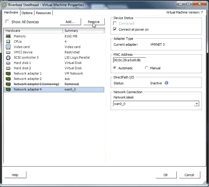
4. Click OK.
5. In the Inventory panel, select the host for the Riverbed SteelHead VM.
6. In the Configuration tab, select Advanced Settings.
7. Click Configure Passthrough.
8. Select all the NICs corresponding to the Riverbed NIC from the list of available direct path devices.
The NICs are identified as Intel 82580 Gigabit Network Connections.
Figure 6‑2. Marking devices for pass-through
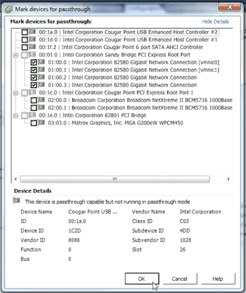
If a NIC is currently in use, vSphere displays a dialog box prompting you to confirm making this NIC a pass-through device. Click Yes to confirm the change.
9. If you are configuring the 10-G fiber card, select the Broadcom Network Controller as a pass-through device.
The Broadcom Controller might appear as Unknown Controller.
10. Click OK.
The NICs appear in the DirectPath I/O Configuration page as available for direct access by the virtual machines on the host.
11. Reboot the host to apply the changes.
12. Ensure the pass-through devices appear correctly.
In the Inventory panel, select the host from the Configuration tab and click Advanced Settings. Review the devices listed in the DirectPath I/O Configuration.
13. In the Inventory panel, right-click the Riverbed SteelHead VM and choose Edit Settings. The Virtual Machine Properties window appears.
In this stage, you add the PCI devices to the VM.
14. Click Add. The Add Hardware dialog box appears.
15. Select PCI Device and click Next.
16. From the Connection menu, choose the PCI device and click Finish.
17. Repeat steps 14 to 16 to add each direct path NIC.
If you are installing a 10-G fiber card, you also need to add the Broadcom Controller as a PCI device.
18. Power on the virtual machine. For DirectPath interfaces, speed and duplex values appear in the interface for LAN and WAN.
To verify NIC installation in the ESXi 5.x host
1. From the SteelHead-v CLI, enter the show interface command.
2. In the DirectPath In-Path Interfaces section, confirm the HW Blockable setting is yes.
3. Confirm the Traffic Status is Normal, Bypass, or Disconnect.
4. If the HW Blockable value is no, enter show hardware all and ensure that the card is one of the cards listed below:
2 Port Copper GigE PCI-E Network Bypass Card, 410-00043-01
4 Port Copper GigE PCI-E Network Bypass Card, 410-00044-01
Two-Port SR Multimode Fiber 10 Gigabit Ethernet Card (Second Generation), 410-00302-02
For details on configuring NICs in the SteelHead-v, see the SteelHead (Virtual Edition) Installation Guide.
Configuring bypass cards for KVM
Complete this procedure to configure a bypass card for SteelHead-v appliances running KVM.
Before you begin
Before you start installation, download the SteelHead-v installation files and host driver files that are specific to the KVM installation from the Riverbed support site at
https://support.riverbed.com.
To configure a NIC bypass card in KVM
1. Enable input-output management unit (IOMMU) mapping on the host machine. The method of enabling IOMMU depends on the type of Linux host and memory chip that is used in the host machine. To enable IOMMU on an Ubuntu host using an Intel card, update the following line in the GRUB file, adding or changing the intel_iommu parameter:
GRUB_CMDLINE_LINUX_DEFAULT="quiet splash acpi=off intel_iommu=on "
2. Download the SteelHead-v installation files, including all the required NIC drivers, from the Riverbed support site at
https://support.riverbed.com.
3. Install the KVM image by following the steps in the SteelHead (Virtual Edition) Installation Guide.
4. Use the install.sh script to install the configure the bypass card.
If using a bypass card with 4 ports, the install.sh script numbers the two left-most physical interfaces as inpath0_0 and the two right-most interfaces as inpath1_0.
Changing the interface numbering with a custom XML file
The following sections describe how bypass cards are assigned interface numbering by default, and how to change the physical interface numbering by creating a custom XML file.
Understanding default interface numbering
If you do not use the default interface numbering by the install.sh file, the numbering is determined by values you specify in an XML file. If you do not specify any values, a PCI device is not explicitly assigned a PCI address in the XML file, and QEMU assigns a PCI address for the device. QEMU assigns the PCI addresses in the order in which the interfaces appear in the XML file, with the interface appearing first in the XML file being assigned a lower device number inside of the VM.
For example, if the PCI IDs of the bypass card network interfaces appear as PCI IDs 04:00.0, 04:00.1, 04:00.3, and 04:00.4, and you specify the IDs in that order in the XML file, the SteelHead-v names the left-most pair of interfaces on the bypass card inpath1_0 and the right-most pair inpath0_0, as shown in this figure.
Figure 6‑3. Physical interface naming
To change the interface numbering, create an XML file and, when entering the PCI address on which the device appears inside the VM, specify the higher-numbered interface pair first. For example, if the four ports of the card in the host machine appear at PCI address 04:00.0, 04:00.1, 04:00.2, and 04:00.3, specify the interfaces in XML file in the order of 04:00.2, 04:00.3, 04:00.0, and 04:00.1, so that the left pair appears as inpath0_0 and the right pair appears as inpath1_0.
To change the default physical interface numbering for a bypass card
1. Identify the PCI IDs of the network interfaces corresponding to the bypass card.
PCI addresses are displayed in the format xx:yy.z, where xx is the bus number, yy is the slot number, and z is the function number.
2. Create an XML file for the SteelHead-v with entries to create the interface numbering.
Use the following guidelines when defining functions:
– Each SteelHead-v LAN/WAN pair must use the same bus number and the same slot number, but must have a different function.
– If one interface of a LAN/WAN pair appears on function 0 in the guest VM, the other interface of the pair must appear on function 1. If one interface of a LAN/WAN pair appears on function 2 inside the guest VM, the other interface must appear on function 3.
– For a 4 port card, 0,1,2, and 3 are the only allowed values the function can take.
– For a 2 port card, 0 and 1 are the only allowed values the function values can take.
The following XML example configures PCI values 04:00.0, 04:00.1, 04:00.3, and 04:00.4 so that the SteelHead-v names the left-most pair of interfaces on the bypass card inpath0_0 and the right-most pair 1_0. The parts of the code that are in bold indicate the values to enter:
– The function values inside the source XML tags (0x2, 0x3, 0x0, and 0x1, respectively) correspond to the function values in the PCI ID on the host.
– The slot and function values outside of the source XML tags (5 and 0x00, 5 and 0x01, 6 and 0x00, and 6 and 0x01 respectively) correspond to the LAN/WAN pair values in the SteelHead-v.
<hostdev mode="subsystem" type="pci" managed="yes">
<source>
<address type="pci" domain="0x0000" bus="0x04" slot="0x00" function="0x2"/>
</source>
<address type="pci" domain="0x0000" bus="0x0" slot="5" function="0x00" multifunction="on"/>
</hostdev>
<hostdev mode="subsystem" type="pci" managed="yes">
<source>
<address type="pci" domain="0x0000" bus="0x04" slot="0x00" function="0x3"/>
</source>
<address type="pci" domain="0x0000" bus="0x0" slot="5" function="0x01" />
</hostdev>
<hostdev mode="subsystem" type="pci" managed="yes">
<source>
<address type="pci" domain="0x0000" bus="0x04" slot="0x00" function="0x0"/>
</source>
<address type="pci" domain="0x0000" bus="0x0" slot="6" function="0x00" multifunction="on"/>
</hostdev>
<hostdev mode="subsystem" type="pci" managed="yes">
<source>
<address type="pci" domain="0x0000" bus="0x04" slot="0x00" function="0x1"/>
</source>
<address type="pci" domain="0x0000" bus="0x0" slot="6" function="0x01" />
</hostdev>
Configuring bypass cards for Hyper-V Server 2012 R2 and 2016
Complete this procedure to configure a bypass card for SteelHead-v appliances running Hyper-V Server 2012 R2 or 2016. Bypass cards are supported on Hyper-v from RiOS 9.7 or later.
Before you begin
Download the SteelHead-v installation files and host driver files that are specific to the Hyper-V installation from the Riverbed support site at https://support.riverbed.com.
The NIC drivers have only been qualified for use with Windows Server 2012 R2 or 2016.
To configure a bypass card in Hyper-V
1. Download the SteelHead-v installation files, including all the required NIC drivers, from the Riverbed support site at
https://support.riverbed.com.
2. Configure, but do not start, the SteelHead-v appliance using the instructions in the SteelHead (Virtual Edition) Installation Guide. Use these configuration options:
– When configuring the appliance using the Virtual Switch Manager, create a virtual switch with a type of Internal.
– Do not include the PowerOn setting, which powers on the appliance after installation is complete. Complete the steps in this procedure before starting the appliance.
After you create the SteelHead-v appliance, four interfaces are created: Aux, Primary, LAN, and WAN.
3. Add a new network adapter and connect it to the virtual switch created above.
After the network adapter is created, the SteelHead-v appliance’s network connections appear in the Network Connections area of the host machine’s Control Panel. This figure shows a new network adapter with a name of mgmt.
Figure 6‑4. SteelHead-v network connections on Hyper-V host machine
4. Begin to install the correct driver by completing the following steps:
– Navigate to the host machine’s Control Panel, right-click the adapter you created, and click Properties.
– Click Install from the vEthernet (mgmt) Properties window
– Select Protocol from the Select Network Feature Type window, then click Add.
– Click Have Disk from the Select Network Protocol window.
Figure 6‑5. Installing the driver software
– Click Browse, select the ndisprot.inf file that you downloaded from the Riverbed support site, then click OK.
– The ndisprot.inf file installs the correct driver software for the network adapter.
5. Open a command prompt as a System Administrator and enter the following command:
net start disprot
6. Start the bpctl service by performing the following tasks:
– From the command prompt, navigate to the directory where the host driver files were extracted.
– Enter the following commands:
.\bpctl.exe install
.\bpctl.exe start
The command prompt displays ok after the service successfully starts.
7. Find the index that corresponds with the internal driver by completing the following steps:
– Enter the following command from the command prompt:
.\bpvmctl.exe -e
– From the command output, match the index in the command output with the driver found in the Network Connections window.
Figure: Finding the index for the interface shows the Ethernet (mgmt) driver having an index of 1.
Figure 6‑6. Finding the index for the interface
8. Enter the following command at the command prompt, where <index> is the index number you identified in
Step 7.
.\bpvmctl.exe -index <index> -r
Leave this command window open; it runs a process that is required for the SteelHead-v’s operation.
9. Add the suffixes A1, A2, A3, and A4 to the SteelHead-v MAC addresses using the Hyper-V user interface.
The MAC addresses allocated by the SteelHead-v installation program have a suffix of A1, A2, A3, or A4. The physical interface ports are mapped in two pairs. The left-most physical interfaces are LAN and WAN pair 2 and map to suffixes A3 and A4. The right-most interfaces are LAN and WAN pair 1 and map to suffixes A1 and A2, as shown in this figure.
Figure 6‑7. LAN pairs 1 and 2
Figure 6‑8. LAN pair 1 with suffix A1
Figure 6‑9. WAN pair 2 with suffix A2