NSV with VRF Select
This section provides an overview of NSV. This section includes the following topics:
Virtual Routing and Forwarding NSV with VRF Select IOS RequirementsPrerequisites for NSVExample NSV Network DeploymentConfiguring NSVVirtual Routing and Forwarding
Virtual routing and forwarding (VRF) is a technology used in computer networks that allows multiple instances of a routing table to coexist within the same router at the same time. VRF partitions a router by creating multiple routing tables and multiple forwarding instances. Because the routing instances are independent, you can use the same or overlapping IP addresses without conflict.
The VRF table is also referred to as the VPNv4 routing table.
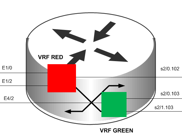
Figure 16‑1. Partitioned Router Using Two Routing Tables
You can implement VRF in a network device by having distinct routing tables, one per VRF. Dedicated interfaces are bound to each VRF.
In
Figure 16‑1, the red table can forward packets between interfaces E1/0, E1/2, and S2/0.102. The green table, on the other hand, forwards between interfaces E4/2, S2/0.103, and S2/1.103.
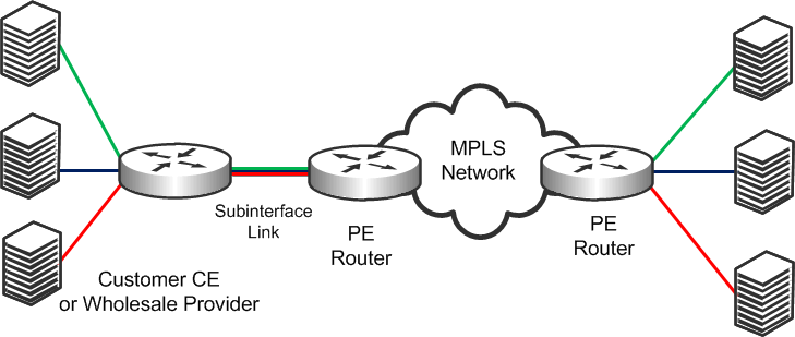
The simplest form of VRF implementation is VRF Lite, as shown in
Figure 16‑2. VRF Lite uses VRFs without multiprotocol label switching (MPLS)
. In this implementation, each router within the network participates in the virtual routing environment in a peer-based fashion. This extends multiple VPNs from a provider edge (PE) device onto non-MLPS customer edge (CE) devices, which support multiple VRFs. It also replaces the requirement for separate, physical CE devices.
Figure 16‑2. VRF Lite
NSV with VRF Select
NSV is a Riverbed network design option that leverages the Riverbed WDS solution by deploying SteelHeads in an existing MPLS deployment using VRF. Riverbed recommends using NSV in an MPLS/VRF environment to deploy SteelHeads while retaining existing overlapping address spaces.
The concept of NSV originates in an MPLS VPN environment with multiple hosts in the same source VPN. The hosts require access to different servers in various destination VPNs. This is a difficult deployment to implement if a particular subinterface is VRF-attached. A subinterface is a way to partition configuration information for certain subsets of traffic that arrive or leave a physical interface.
NSV uses the IOS MPLS VPN VRF Select feature, which essentially eases the requirement of a VRF-attached subinterface.
The VRF Select feature uses policy-based routing (PBR) at the ingress interface of the VRF router to determine which VRF to forward traffic to. In most cases, the VRF router is a PE device. In a VRF-Lite implementation, the VRF router is a CE device. The VRF router determines the routing and forwarding of packets coming from the customer networks (or VPNs). The access control list (ACL) defined in the PBR route map matches the source IP address of the packet. If it finds a match, it sends the packet to the appropriate MPLS VPN (the VRF table).
The VRF table contains the virtual routing and forwarding information for the specified VPN. It forwards the selected VPN traffic to the correct MPLS label switched path (LSP), based upon the destination IP address of the packet.
NSV with VRF Select removes the association between the VRF and the subinterface. Decoupling the VRF and the subinterface allows you associate more than one MPLS VPN to the subinterface. The subinterface remains in the IPv4 dimension in VRF Select (as compared to the VPNv4 address space, in which it resides when it is VRF-attached). The subinterface is still IPv4-based, but it becomes aware of VRF Select by replacing the ip vrf forwarding Cisco command with ip vrf receive command.
The result is that the subinterface becomes Not-So-VRF. The subinterface still resides in the global IPv4 table, but it now uses PBR for the VRF switch. The PBR route map matches criteria based on traffic flows to be optimized.
IOS Requirements
Cisco recommends the following minimum IOS releases for an MLPS VPN VRF Selection using PBR deployment.
Cisco Hardware | Cisco IOS |
Most Router Platforms | 12.3(7)T or later |
C76xx | 12.2(33)SRB1, 12.2(33)SRB2, 12.2(33)SRC, 12.2(33)SRC1, 12.2(33)SRC2 |
ASR 1000 Series Router | XE 2.1.0, 2.1.1, 2.1.2, 2.2.1 |
Regardless of how you configure a SteelHead, if the Cisco IOS version on the router or switch is below the current Cisco minimum recommendations, it might be impossible to have a functioning NSV implementation, or the implementation might not have optimal performance.
Prerequisites for NSV
Before configuring NSV, review the following information:
A detailed network diagram illustrating the logical connectivity between the data centers and branch officesA running configuration of the multiple VRF CE devicesThe exact IOS versions and hardware platforms in useExample NSV Network Deployment
This example shows the following deployment scenario:
One SteelHead, configured as a logical in-path (data center)One SteelHead, configured as a physical in-path (branch office)Both SteelHeads are running RiOS v5.0.3 or laterThe operating system is 12.3(15)T7 Two units of 3640 series routersTwo units of WinXP VM hostsIP Service Level Agreement (SLA) Static routes with trackingThis deployment is the basis for the configuration shown in
Configuring NSV.
Figure 16‑3 shows a logical in-path NSV deployment in a VRF network environment.
Figure 16‑3. Sample NSV Network Setup
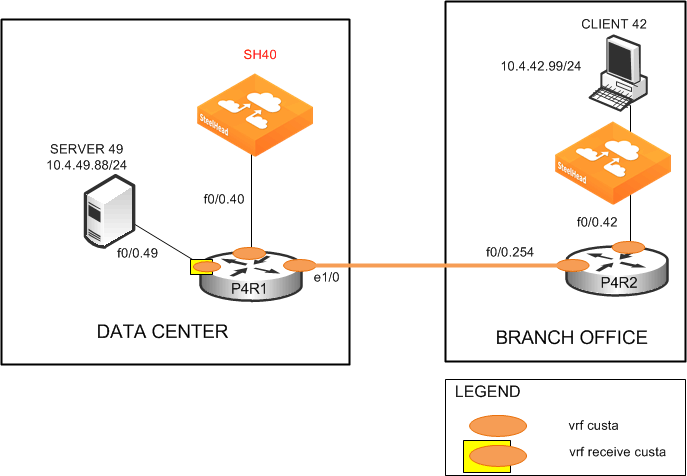
Figure 16‑4 shows the NSV deployment shown in
Figure 16‑3 with intercepted and optimized flows.
Figure 16‑4. NSV Deployment with Intercepted and Optimized Flows
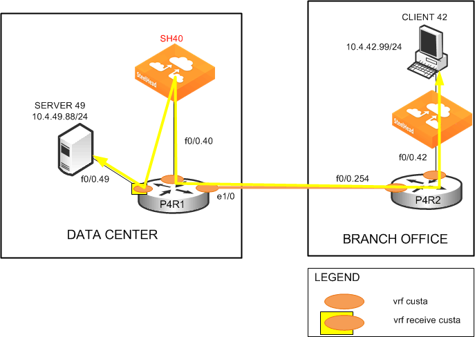
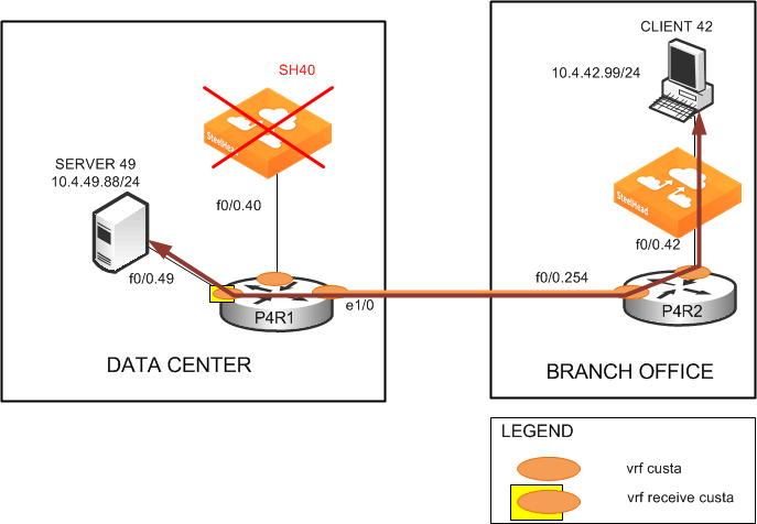
Figure 16‑5 shows the NSV deployment with bypassed flows in the event that the data center SteelHead fails.
Figure 16‑5. NSV Deployment with Bypassed Flows
Configuring NSV
This section describes how to configure NSV. This section includes the following topics:
Basic Steps for Configuring NSV Configuring the Data Center RouterConfiguring the PBR Route MapDecoupling VRF from the Subinterface to Implement NSVConfiguring Static RoutesConfiguring the Branch Office Router Configuring the Data Center SteelHeadConfiguring the Branch Office SteelHead The configuration in this section uses the parameters set up in
Example NSV Network Deployment.
Basic Steps for Configuring NSV
This section shows the overview of the basic steps to configure NSV with VRF Select. The following sections describe each step in detail.
To configure basic NSV with VRF select
Configure the data center PE or CE router, which includes defining:
the VRF tables. the subinterfaces. the PBR route map. PBR.static routes. parameters for monitoring the SteelHead availability.Configure the branch office router.
Configure the data center SteelHead.
Configure the branch office SteelHead.
The following sections describe each of these steps in detail.
Configuring the Data Center Router
The data center PE or CE router determines the routing and forwarding of packets coming from the customer networks or VPNs. This device requires the most configuration.
The first step is to define the VRF tables for the SteelHead. For example, you define two VRF tables for SteelHead 40: custa for the customer and wds_a to use as a dummy VRF table. The dummy VRF table is not tied to any interface. It redirects traffic with a corresponding default route, which points to or exits at the subinterface to the SteelHead.
You cannot enter the set ip next-hop Cisco command on a PBR route map configured for VRF select.
The next step configures the subinterfaces and VRF routing protocol. In this example, you configure the following subinterfaces and define the OSPF VRF routing protocol:
f0/0.40 (the LAN-to-SteelHead 40)e1/0 (the WAN)This example uses OSPF as the routing protocol, but you can use other protocols, such as RIP, EIGRP, ISIS, and BGP, as well. OSPF uses a different routing process for each VRF. For the other protocols, a single process can manage all the VRFs.
To define the VRF tables and subinterfaces
Define the VRF tables for the SteelHead. On the data center router (in this example, P4R1), enter the following commands:
hostname p4R1
!
ip cef
!
ip vrf custa
rd 4:1
!
ip vrf wds_a
rd 4:9
!
Configure the VRF subinterfaces and corresponding VRF routing protocol. On the data center router, at the system prompt, enter the following commands:
interface FastEthernet0/0.40
encapsulation dot1Q 40
ip vrf forwarding custa
ip address 10.4.40.1 255.255.255.0
!
interface Ethernet1/0
ip vrf forwarding custa
ip address 10.254.4.1 255.255.255.0
half-duplex
!
router ospf 4 vrf custa
redistribute static subnets
network 10.4.40.0 0.0.0.255 area 0
network 10.254.4.0 0.0.0.255 area 0
This example configures the LAN subinterface f0/0.40, which interconnects SteelHead 40 to use VRF custa. Later, you point the dummy VRF wds_a to a default route (in this example, f0/0.40). This enables a PBR route map at f0/0.49 to redirect incoming traffic from Server 49 to Client 42 to SteelHead 40 for optimization.
In this example, because Client 42 is in the VPN custa (VRF custa), the traffic must return to the VRF custa routing path after optimization. For this redirection to work, the SteelHead 40 must reside in VRF custa and not VRF wds_a.
Configuring the PBR Route Map
VRF Select requires a control mechanism such as PBR to select which particular VRF table a data packet goes to. The next step is to configure a PBR route map, which provides a matching criteria for incoming traffic and sets the VRF table.
To configure the PBR route map
On the data center router, enter the following commands:route-map wds_a permit 10
match ip address 104
set vrf wds_a
!
route-map wds_a permit 20
set vrf custa
!
access-list 104 permit tcp host 10.4.49.88 host 10.4.42.99
The route map wds_a matches incoming traffic from Server 49 to Client 42. When it finds a match, it sets the VRF to wds_a, which, in turn, points to default route f0/0.40, where SteelHead 40 resides. Binding f0/0.40 with VRF custa ensures that the returning optimized traffic eventually reaches Client 42. The route map also sets any incoming traffic to VRF custa—except Server 49 to Client 42.
Ensure that the PBR route map contains a default set vrf in the PBR route map to always match a packet that does not match any of the previous criteria.
Because BGP control packets are required to remain categorized as global-IPv4, use an ACL to ensure that these packets do not get forwarded to a VRF table.
Decoupling VRF from the Subinterface to Implement NSV
The following step decouples the association between VRF and a subinterface. It implements NSV by replacing the ip vrf forwarding Cisco command with ip vrf receive command.
The result is that the subinterface is becomes Not-So-VRF. The subinterface still resides in the global IPv4 table, but it now uses PBR for the VRF switch. The PBR route map matches criteria based on traffic flows to be optimized.
To implement VRF Select and PBR
On the data center router, enter the following commands:interface FastEthernet0/0.49
encapsulation dot1Q 49
ip vrf receive custa
ip address 10.4.49.1 255.255.255.0
ip policy route-map wds_a
The absence of the ip vrf forwarding command in this example configuration implies that f0/0.49 is not associated with any particular VRF and remains in the IPv4 global address space. This makes it possible for the SteelHeads to communicate with the subinterface.
Configuring Static Routes
Static routes play a crucial role in an NSV deployment, because you use them to fine-tune the routing. The primary, default static route points to the in-path interface to redirect incoming traffic for optimization. (In the following example, traffic is redirected to 10.4.40.101 of SteelHead 40).
The command keyword track 1 determines whether the in-path IP address of the SteelHead is reachable. The primary, default static route is used only when the in-path IP address for the SteelHead is reachable. If it becomes unreachable, the primary route is removed from the routing table. The second, floating route serves as a backup to avoid blackholing traffic and ensure flow continuity.
In this example, when the primary route is removed from the routing table because the SteelHead is unreachable, the second route becomes effective at an administrative weight of 250, points to the WAN interface e1/0, and avoids blackholing traffic to ensure flow continuity.
Also, in this example, because f0/0.49 (where Server 49 is connected) is still in the IPv4 global address space, you must make it visible in VRF custa. To do this, you assign a third static route, associating it with VRF custa. The third static route points to Server 49 (10.4.49.88) in VRF custa and redistributes it into OSPF.
To define static routes
On the data center router, enter the following commands:ip route vrf wds_a 0.0.0.0 0.0.0.0 FastEthernet0/0.40 10.4.40.101 track 1
ip route vrf wds_a 0.0.0.0 0.0.0.0 Ethernet1/0 10.254.4.2 250
ip route vrf custa 10.4.49.88 255.255.255.255 FastEthernet0/0.49 10.4.49.88
!
To monitor SteelHead availability
On the P4R1, at the system prompt, enter the following commands:ip sla monitor 1
type echo protocol ipIcmpEcho 10.4.40.101
vrf custa
frequency 5
!
ip sla monitor schedule 1 life forever start-time now
!
track 1 rtr 1 reachability
IP SLA uses the ICMP echo protocol to monitor the availability status of the SteelHead in-path IP address every 5 seconds (in this example, IP address 10.4.40.101 for SteelHead 40:custa). This is tied to the primary default route through the tracking mechanism. The tracking mechanism prevents routing to an unavailable IP destination when the in-path IP address for the SteelHead is down (in this example, SteelHead 40:custa).
Configuring the Branch Office Router
A typical branch office router is a PE VRF or CE VRF Lite device. Its configuration is minimal and standard. In most environments you probably do not need to configure this device.
To configure the P4R2
On the P4R2, enter the following commands:hostname P4R2
ip cef
ip vrf custa
rd 4:1
interface FastEthernet0/0.42
encapsulation dot1Q 42
ip vrf forwarding custa
ip address 10.4.42.1 255.255.255.0
interface FastEthernet0/0.254
encapsulation dot1Q 254
ip vrf forwarding custa
ip address 10.254.4.2 255.255.255.0
router ospf 4 vrf custa
network 10.4.42.0 0.0.0.255 area 0
network 10.254.4.0 0.0.0.255 area 0
Configuring the Data Center SteelHead
The data center SteelHead (in this example, VRF custa) is another vital component of an NSV deployment. Its configuration is very simple; you simply enable the logical in-path interface.
To configure the data center SteelHead
On the data center SteelHead, connect to the CLI and enter the following commands: hostname "SH40"
interface inpath0_0 ip address 10.4.40.101 /24
ip in-path-gateway inpath0_0 "10.4.40.1"
in-path enable
in-path oop enable
write memory
restart
You must save your changes or they are lost upon reboot. Restart the optimization service for the changes to take effect.
Configuring the Branch Office SteelHead
The SteelHead deployed at the branch office needs slightly more configuration than the data center SteelHead. Because you are only implementing VRF Select for redirecting the data center LAN-side traffic, you must define fixed-target rules for the WAN-side traffic.
The following example uses SteelHead 42:custa.
To configure the branch office SteelHead:
On the branch office SteelHead, connect to the CLI and enter the following commands: hostname "SH42"
interface inpath0_0 ip address 10.4.42.101 /24
ip default-gateway "10.4.42.1
in-path enable
in-path rule fixed-target target-addr 10.4.40.101 target-port 7800 dstaddr
10.4.49.88/32 dstport "all" srcaddr 10.4.42.99/32 rulenum 4
You must save your changes or they are lost upon reboot. Restart the optimization service for the changes to take effect.
You can also use auto-discovery to eliminate configuring fixed-target rules if you disassociate the WAN interface (in this example, P4R1
e1/0) from the VRF
(in this example, custa) the same way you disassociated the LAN interface using VRF select as described in
Decoupling VRF from the Subinterface to Implement NSV.
The branch office SteelHead could also be a SteelHead Mobile. In this deployment, you could use the Mobile Controller to facilitate configuring the fixed-target rules.
For information about the Mobile Controller, see the SteelCentral Controller for SteelHead Mobile User’s Guide.