VLAN Bridging Deployments
This section describes the use of virtual LAN (VLAN) bridging. This section includes the following topics:
Overview of VLAN Bridging DeploymentVLAN Bridging ConsiderationsVLAN Bridging VariationsOverview of VLAN Bridging Deployment
The term VLAN bridging refers to a network design in which both the LAN and WAN ports of a SteelHead's in-path interface are connected to a single switch or router. The switch or router is then configured so that traffic to be optimized must pass through the SteelHead—by forcing the traffic's Layer-2 path to or from the WAN to pass through the in-path interface.
VLAN bridging is useful in network environments in which it is difficult to install a SteelHead physically in-path. For example, if fiber interfaces are needed for a physical in-path installation, but only copper interfaces are available on the SteelHead, you can use VLAN bridging as a simpler alternative to WCCP or PBR.
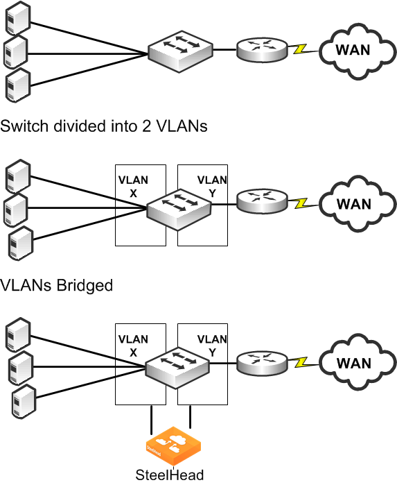
Figure 9‑23 shows the principles of VLAN bridging. An existing switch or router is divided into two separate VLANs, and the SteelHead's LAN and WAN interfaces are used as the Layer-2 bridge that connects the VLANs.
Figure 9‑23. VLAN Bridging Principles

VLAN Bridging Considerations
A VLAN bridging deployment has the same features and functionality as a physically in-path SteelHead, with the exception of 802.1Q VLAN trunking.
Consider the following when you use a VLAN bridging deployment:
You can use an 802.1Q trunk with VLAN bridging between multiple VLANs on the same in-path interface, but this requires switch-specific features. Use the same cables for the WAN and LAN interfaces—the same as you use for physical in-path deployments. The switch detects the same MAC addresses in two different VLANs. Because most switches have separate MAC address tables per VLAN (independent VLAN learning, or IVL), some older switches can have only one MAC table for all VLANs (shared VLAN learning). Use only switches that have IVL with VLAN bridging. Verify that the switch allows access to its management IP address from multiple VLANs. Avoid using a switch whose management IP is only reachable from the default VLAN, because this prevents managing the switch. Some switches assign their management IP address to the default VLAN, and cannot be altered—for example, the Cisco 2950 switch. VLAN Bridging Variations
The variations of VLAN-Bridging are as follows:
Layer-2 VLAN BridgingLayer-3 VLAN BridgingMultiple VLAN Bridging with VLAN MappingLayer-2 VLAN Bridging
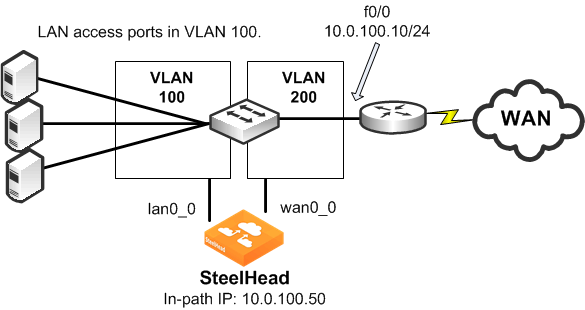
In a Layer-2 VLAN bridging deployment, the SteelHead is connected by VLANs on the Layer-2 switch. All traffic is bridged through the SteelHeads as it passes to and from the WAN routers.
Figure 9‑24 shows a Layer-2 VLAN bridging deployment.
Figure 9‑24. Layer-2 VLAN Bridging

Note the following:
VLAN 100 and VLAN 200 are Layer-2 VLANs.The default gateway of the hosts on the LAN must point to the router interface IP address.VLAN 100 contains the switch ports of the hosts and the switch port connected to the lan0_0 interface of the SteelHead.VLAN 200 contains the switch ports, the router, and the wan0_0 interface of the SteelHead.The default gateway of the SteelHead is the IP address of the WAN router.Layer-3 VLAN Bridging
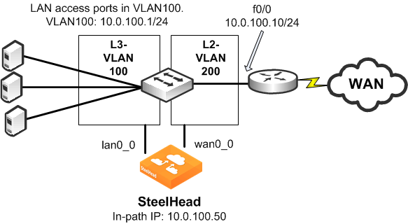
In a Layer-3 VLAN bridging deployment, the SteelHead is connected across Layer-3 and Layer-2 VLANs on a Layer-2/Layer-3 switch. All traffic is switched through the SteelHead as it passes to and from the WAN router.
Figure 9‑25 shows a Layer-3 VLAN bridging deployment.
Figure 9‑25. Layer-3 VLAN Bridging

Note the following:
Hosts on the VLAN 100 must point to VLAN 100 IP address as the default gateway. VLAN 100 contains the switch ports of the hosts, and the switch port connected to the lan0_0 interface of the SteelHead.VLAN 200 contains the switch ports, the router, and the wan0_0 interface of the SteelHead connect to.The default gateway of the SteelHead is the IP address of the WAN router.Multiple VLAN Bridging with VLAN Mapping
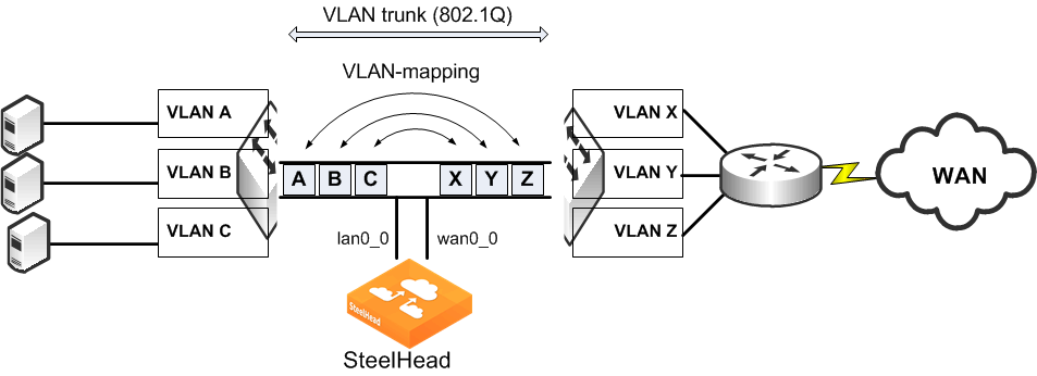
A limitation in Layer-2 VLAN bridging and Layer-3 VLAN bridging is that a single in-path interface can only bridge two different VLANs. If the SteelHead-connected switch ports are configured to be 802.1Q trunks (so that many VLANs can be sent or received), the switch does not bridge traffic for the VLANs across the ports.
To connect to multiple VLANs, you need a switch that supports
VLAN mapping (also referred to as
VLAN translation or
VLAN normalization, depending on the switch vendor). VLAN mapping allows a trunk interface to change the 802.1Q tag. You must configure the switch with the mapping of one VLAN tag (used on the LAN side of the SteelHead) to another VLAN tag (used on the WAN side of the SteelHead) for packets to be sent or received.
Figure 9‑26 shows multiple VLAN bridging with VLAN mapping deployment.
Figure 9‑26. Multiple VLAN Bridging with VLAN Mapping

The following functionality makes it possible to optimize multiple VLANs with VLAN bridging:
The VLAN mapping function on a switch changes the VLAN tags. A SteelHead cannot do this. VLAN mapping takes 802.1Q tagged traffic from an incoming trunk switch-port and maps it to a different local VLAN. For information about configuring your specific hardware, refer to the documentation provided with your switch.


