Valid Path Selection Deployment Design Examples
The section shows valid path selection deployment examples. The examples in this section show only one side of the WAN. You must assume that the remote side also has similar path selection capabilities and configurations for symmetric for return traffic. This section includes the following topics:
Basic Multiple Route Path DeploymentComplex Parallel Path DeploymentComplex Single In-Path Interface DeploymentSerial DeploymentFirewall Path Traversal DeploymentBasic Multiple Route Path Deployment
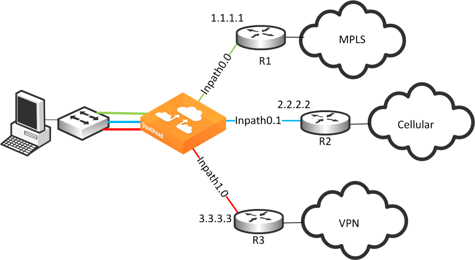
Figure 8‑9 shows a SteelHead connected to three separate routers on three distinct in-path connections. Inpath0_0 is connected to Router 1, which is serving an MPLS connection. Inpath0_1 is connected to Router 2, which is serving a cellular-based WAN connection. Inpath1_0 is connected to Router 3, which is serving a VPN-based connection.
Figure 8‑9. Basic Multiple Route Path Deployment
To configure path selection on the SteelHead as shown in
Figure 8‑9From the Management Console, choose Networking > Topology: Sites & Networks.
Select Add a Network and create a separate network for each of the three different carriers, labeling each path with the proper name as shown in
Figure 8‑10.
Figure 8‑10. Three Path Selection Networks

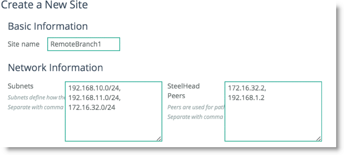
Scroll down and select Add a Site (
Figure 8‑11). The Subnets field is composed of the local subnets situated on the LAN side of the SteelHead. The SteelHead Peers field is a collection of remote IP addresses you want to probe to validate the path status.
Figure 8‑11. Add a New Site
Repeat
Step 3 for all remote sites in the path selection design.
To configure remote sites you are required to enter the remote site name, IP segments residing at that remote site, and peer IP addresses to probe to determine path availability.
Click
Edit Site for the Local site, change the site name, and properly assign the Network label according to the proper in-path interface as shown in
Figure 8‑12.
Figure 8‑12. Editing the Local Site
Click Save.
Choose Networking > Network Services: Path Selection.
Select Enable Path Selection and click Save.
Scroll down and select Add a Rule.
Configure the application with the desired path order.
Select the specific application or entire Application Group. Next, select the destination site, and choose the uplink interface in order of preference.
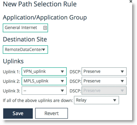
Figure 8‑13 shows an application group of type
General Internet is selected to be steered through the VPN path, followed by MPLS if VPN is not available.
Figure 8‑13. Configuring Path Selection for Application General Internet
Complex Parallel Path Deployment
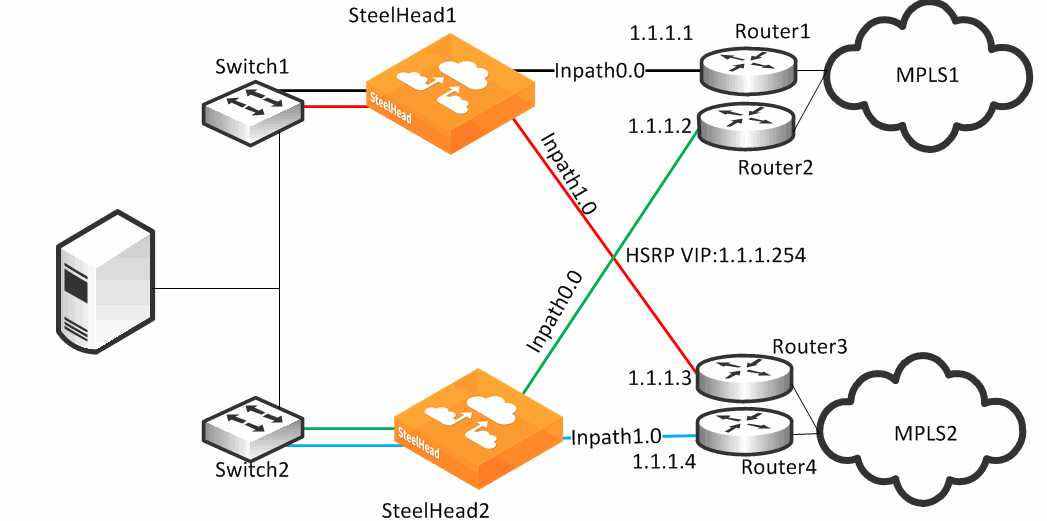
Figure 8‑14 shows a dual parallel SteelHead deployment on the WAN side with a four-way HSRP design. On the WAN side, Router 1 and 2 connect to the MPLS1 provider, and Router 3 and 4 connect to the MPLS2 provider. On the LAN side, each switch has a connection to both providers through a separate router.
Figure 8‑14. Complex Parallel Path Deployment
While each of the links in
Figure 8‑14 can also be individual Layer-3 links, in this example there are two networks with HSRP configured on each network. When you define uplinks, use the real IP addresses of the routers as the gateway, and not the virtual IP address. If you use a virtual IP address, you can cause the gateway to reside on the LAN side of the SteelHead in-path interface, resulting in unintended traffic flow. If your design is configured with a single HSRP group covering both routers, you must use the real IP address of the router as the gateway, and not the virtual IP address.
Each SteelHead is connected to each router with the MPLS provider; therefore, both SteelHeads can make uniform path selection decisions, with traffic moving toward the same router and provider.
Riverbed recommends that you configure both SteelHeads with equivalent paths, uniform path selection rules and logic.
Figure 8‑14 shows SteelHead configured with two networks: MPLS1 and MPLS2.
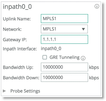
Figure 8‑15 shows the network topology configuration of SteelHead1 from
Figure 8‑14.
Figure 8‑15. SteelHead1 Network Topology Configuration

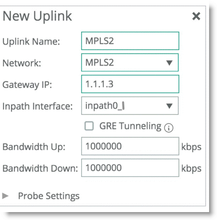
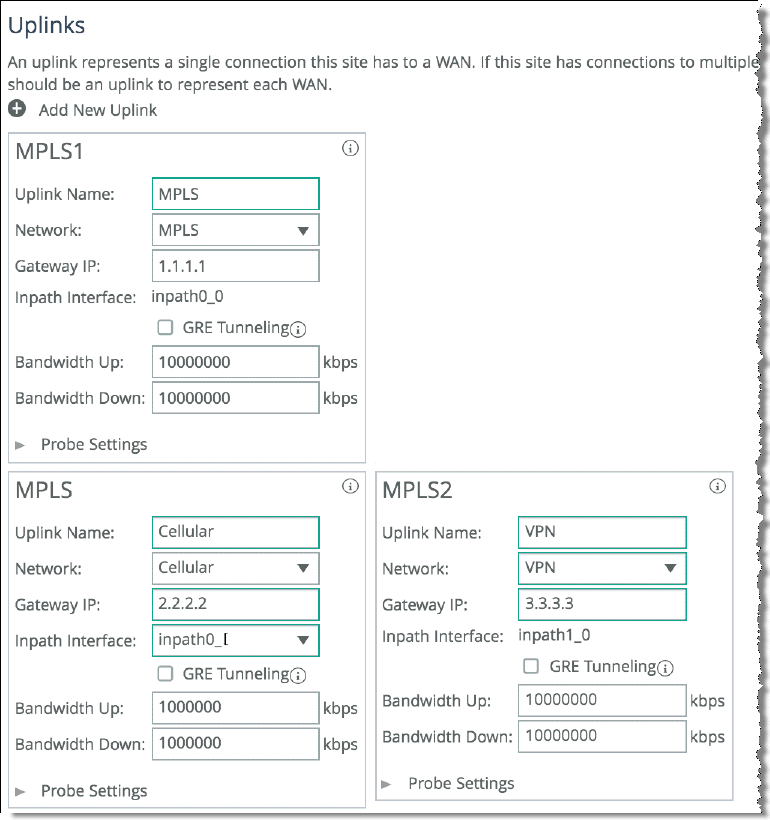
Figure 8‑16 shows SteelHead1 uplink configuration.
Figure 8‑16. SteelHead1 Uplink Configuration
SteelHead2 is configured with the equivalent paths, but with the respective gateway of Router2 IP address 1.1.1.2 and Router4 IP address 1.1.1.4.
If your design includes a single HSRP group covering both routers, configure SteelHead2 so that it is identical to that shown in
Figure 8‑16, in which the path gateway references the real IP interface and not the virtual IP.
Complex Single In-Path Interface Deployment
Figure 8‑17 shows the SteelHead connected through a single in-path interface connection, but the WAN side is composed of multiple WAN routers, each to their own separate provider. Note that the LAN side of the routers all share the same IP segment. Because they share the same IP segment, achieving path selection configuration in this setup is valid, because the SteelHead can be configured with different gateway addresses traversing the same in-path interface. You must configure a router gateway redundancy mechanism, such as HSRP or VRRP. This configuration needs a redundancy mechanism, because the SteelHead does not act as the default gateway for the clients.
This is completed using multiple uplinks for a single in-path.
Figure 8‑17. Complex Single In-Path Interface Deployment
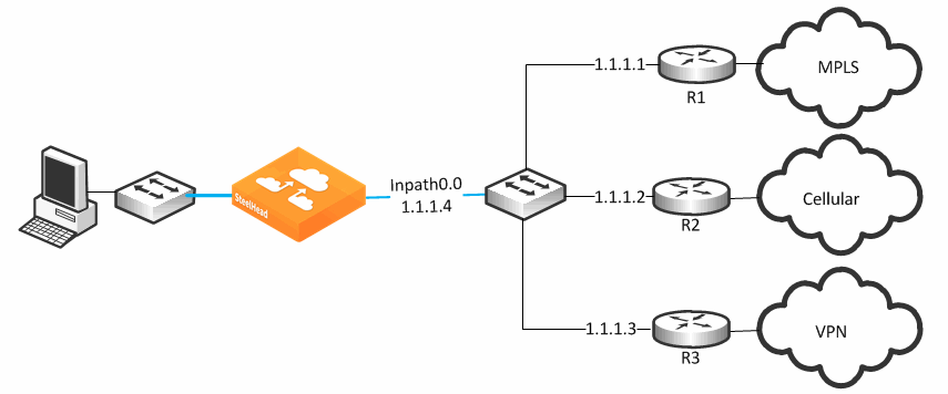
Figure 8‑18 shows the network topology configuration for
Figure 8‑17.
Figure 8‑18. SteelHead1 Network Topology Configuration

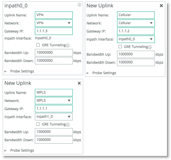
Figure 8‑19 represents the uplink configuration for the deployment shown in
Figure 8‑17. The Local Site uplink configuration reflects additional uplinks each associated with a separate network in which each uplink shares the same inpath0_0 as the egress interface, but the gateway IP differs for each network desired.
Figure 8‑19. Uplink Configuration
A complex single in-path interface deployment is valid for path selection when all the routers are on the same subnet as the SteelHead single in-path interface. If the in-path interface is on an 802.1Q trunk, you cannot use path selection to direct traffic to different routers on different VLANs. The switch shown in
Figure 8‑17 is a Layer-2 switch, and therefore path selection can make the decision to send traffic to the appropriate router MAC address.
Serial Deployment
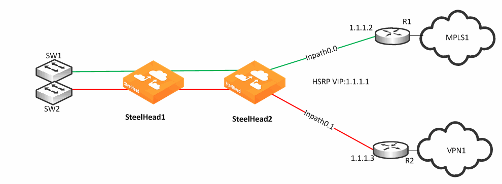
Figure 8‑20 shows a dual serial SteelHead deployment. SteelHead 1 is the client SteelHead, and SteelHead 2 is referred to as the
middle file engine (MFE). On the WAN, Router 1 is connected to the MPLS provider, and Router 2 connects to the customer internal network using a VPN connection. In this example, Riverbed recommends that you use the real IP address of the router as the path gateway instead of the virtual IP provided by HSRP and VRRP.
Figure 8‑20. Serial Deployment
You can use path selection in a serial deployment if:
SteelHeads have identical path selection configuration.correct addressing is in use, you must configure SteelHead 2 to relay the inner channel of SteelHead 1.you are using Full Transparency, you must use the path-selection settings bypass non-local-trpy enable command on SteelHead 2.Firewall Path Traversal Deployment
This section describes how to configure firewall path traversal deployment. This section contains the following topics:
MTU and MSS Adjustment When Using Firewall Path TraversalFirewall Path Traversal Deployment ExampleStateful firewall devices typically provide security services including:
tracking the TCP connection state.blocking a sequence of packets.Stateful security devices add a level of complexity to path selection environments when the SteelHead attempts to make any path changes to a connection midstream. The most common examples of midstream switching are:
failure of a higher-priority path, failing to firewall path. recovery of path, resuming traffic to a firewall path. using AFE for identification because the first packets of a connection are not recognized yet and can traverse a default path. When a path changes midstream, the stateful firewall device is likely to see only some or none of the packets necessary to keep state and sequence numbers. When receiving packets are perceived to be out of order or belonging to a connection with inaccurate state information, stateful firewalls generally drop these packets.
Beginning with RiOS 8.6, Riverbed recommends that you use the firewall path traversal capability to leverage GRE tunneling over paths traversing a stateful firewall. When you use standard GRE between SteelHeads, connections can be switched midstream because the firewall only detects the encapsulated packets. You can configure GRE tunneling per uplink, and when enabled, the SteelHead attempts to encapsulate packets to the remote SteelHead at the configured remote peer IP address. The peer IP address needs to be an in-path IP address of a remote SteelHead. You can use multiple uplinks using GRE tunneling between the same SteelHeads, and the original packet or QoS-configured DSCP values are reflected in the GRE packets.
There is a loss of visibility on the firewall when you use GRE encapsulation. You also might need additional configuration on the firewall to allow the GRE packets between SteelHeads.
MTU and MSS Adjustment When Using Firewall Path Traversal
When you use GRE tunneling, consider that there is an additional 24-byte overhead added to packets. This overhead can cause fragmentation of large packets, because the extra added bytes cause the packet to exceed the maximum transmission unit (MTU) configured in the network. Fragmentation has the negative effect of sending inefficiently sized packets, and dropping packets that might have the do not fragment option set.
You can prevent fragmentation by adjusting the maximum TCP payload, or MSS value, to account for the overhead added by GRE. When you configure a path with the tunnel mode set to GRE, the SteelHead measures to reduce potential fragmentation for TCP traffic.
This automatically applied MSS value ensures that in most environments TCP packets are not fragmented, even with the additional GRE overhead. In an optimized case, the client and server connections with the SteelHead are not impacted by the MSS adjustment procedure. For pass-through TCP traffic, the SteelHead adjust the MSS value to make room for a GRE header. To turn off this automatic MSS adjustment, use the command no path-selection settings tunnel adjust-mss enable.
For more information about MTU, see
MTU Sizing.
Firewall Path Traversal Deployment Example
Figure 8‑21 shows a dual-parallel installation of SteelHeads in a dual-homed WAN scenario. In this example, a firewall is installed on the edge of the Internet path. The SteelHead has visibility into both MPLS and VPN paths.
Figure 8‑21. Firewall Path Deployment
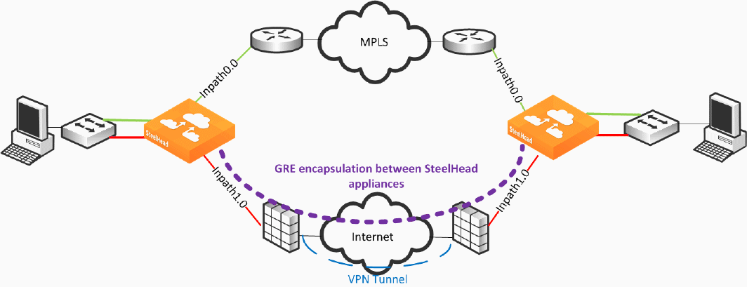
There are two uplinks defined: the green uplink over MPLS and the red uplink traversing stateful firewall devices. The firewall path is configured for GRE tunneling between the SteelHeads. When you configure a path for GRE encapsulation, it affects only the decision of the local SteelHead in that the opposing SteelHead must also have similar path configuration for return traffic to be encapsulated.
Note that the SteelHeads are not providing the VPN functionality over the Internet, but sending traffic over the VPN tunnel provided by the existing firewalls in the path. Remember that this SteelHead configuration for path traversal over firewalls uses standard GRE encapsulation, which is not a secure method of traversing the Internet.
In addition, the firewalls provide other necessary functions, such as NAT, and Riverbed does not recommend that you to use the SteelHead GRE capability instead of direct VPN functionality.
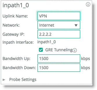
GRE tunneling configuration is enabled during the uplink setup (
Figure 8‑22). You must denote the remote SteelHead in-path IP address in the peer setup field in order to terminate the GRE tunnel.
Figure 8‑22. GRE Tunneling
