Replacing Memory
This section describes how to replace memory in the xx50 appliances.
DIMM Slot Locations
Memory modules and slot locations vary according to the motherboard in your appliance. Before you begin, you must obtain the correct replacement memory and slot location from Riverbed Support. The following figures identify the slot location for the memory modules according to the hardware platform.
DIMM Slot Locations in SteelHead 150, 250, and 550 Appliances
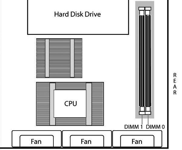
The following diagram shows the memory module slot locations for SteelHead 150, 250, and 550 appliances.
Figure: Memory Module Slots in SteelHead 150, 250, and 550 Appliances
DIMM Slot Locations in Interceptor 9350 Appliances
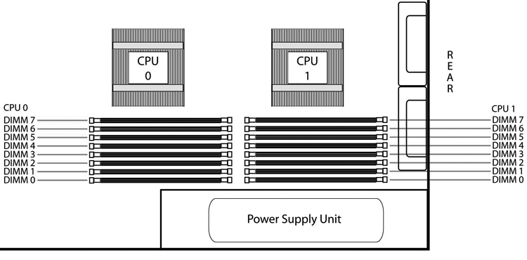
The following diagram shows the memory module slot locations for Interceptor 9350 appliances.
Figure: Memory Module Slots in Interceptor 9350 Appliances
Replacing Memory Modules in SteelHead 150, 250, and 550 Appliances
This section describes how to replace memory modules in a SteelHead 150, 250, and 550 appliance.
Before you begin, work with Riverbed Support at https://support.riverbed.com to determine the type of memory for the motherboard in your appliance and to determine the correct slot location for the memory. Memory modules and slot locations vary according to the motherboard in your appliance.
When replacing memory, you must use approved memory modules. Contact your Riverbed sales representative to obtain the correct memory modules.
Note: When you replace memory modules, you must wear a grounded ESD antistatic strap to protect the hardware against electrostatic discharge. Make sure that the strap makes skin contact prior to handling equipment. For details, see
Electrostatic Discharge Guidelines.
To replace the memory modules
1. Power down the system.
2. Disconnect the appliance from the electrical outlet and peripherals.
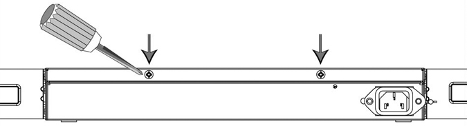
3. Remove the two locking screws on the back of the chassis.
Figure: Removing the Locking Screws
4. Position your thumbs on the top of the appliance and slide the cover back from the chassis.
5. Carefully lift the cover away from the appliance.
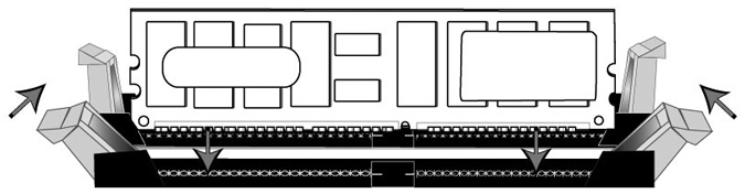
6. Press the ejector tabs on the memory slots down and outward, and gently pull the memory module out of the slot.
Caution: 
Be careful not to touch the adjacent power supply unit. Touching the power supply unit could cause electric shock.
Figure: Accessing the Memory Modules
7. If you are replacing memory, remove the existing memory module and replace it with the approved memory module.
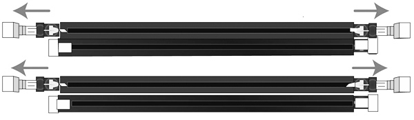
8. Align the memory-module edge connector with the slot alignment keys and insert it into the slot. The module slot has two alignment keys that allow you to install the module in only one direction.
Figure: Inserting and Securing the Memory Module in the DIMM Slot
9. Press down on the memory module with your thumbs while pulling up on the ejectors with your index fingers to lock the module into the slot.
10. Ensure that all ejector tabs are in the upright locked position.
11. Replace the chassis cover.
Replacing Memory Modules in 1U xx50 Appliances
This section describes how to replace memory modules in a 1U appliance. Before you begin, you must obtain the correct replacement memory and slot location from Riverbed Support. Memory modules and slot locations vary according to the motherboard in your appliance.
Contact Riverbed Support at https://support.riverbed.com to determine the type of memory and slot location for the motherboard in your appliance.
Note: When you replace memory modules, you must wear a grounded ESD antistatic strap to protect the hardware against electrostatic discharge. Make sure that the strap makes skin contact prior to handling equipment. For details, see
Electrostatic Discharge Guidelines.
To replace the memory modules
1. Power down the system.
2. Disconnect the appliance from the electrical outlet and peripherals.
3. Carefully lift the cover away from the appliance.
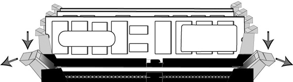
4. Press the ejector tabs on the memory slots down and outward, and gently pull the memory module out of the slot.
Figure: Accessing the Memory Modules
5. Remove the existing memory module and replace it with an approved memory module of the same size.
Note: Replacing the existing memory module with a module of a different size causes the system to fail. You must use approved memory modules. Contact Riverbed Support at https://support.riverbed.com to obtain the correct memory modules.
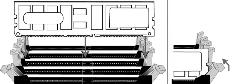
6. Align the memory-module edge connector with the slot alignment keys and insert it into the slot. The module slot has two alignment keys that allow you to install the module in only one direction.
Figure: Inserting the Memory Modules into the Connector Slot and Securing
7. Press down on the memory module with your thumbs while pulling up on the ejectors with your index fingers to lock the module into the slot.
8. Ensure that all ejector tabs are in the upright locked position.
9. Repeat Step 3 to Step 7 of this procedure to install the remaining memory modules.
10. Replace the chassis cover.
Replacing Memory Modules in 3U xx50 Appliances
This section describes how to replace memory modules in 3U appliances. Before you begin you must obtain the correct replacement memory and slot location from Riverbed Support. Memory modules and slot locations vary according to the motherboard in your appliance.
Contact Riverbed Support at https://support.riverbed.com to determine the type of memory and slot location for the motherboard in your appliance.
Note: When you replace memory modules, you must wear a grounded ESD antistatic strap to protect the hardware against electrostatic discharge. Make sure that the strap makes skin contact prior to handling equipment. For details, see
Electrostatic Discharge Guidelines.
To remove the appliance cover
1. Power down the system.
2. Disconnect the appliance from the electrical outlet and peripherals.
3. Remove the top cover of the chassis.
To access the memory modules in the Interceptor 9350 appliances, you must remove the appliance cooling shroud. The following figures illustrate the necessary steps to remove the cooling shroud.
To remove the cooling shroud
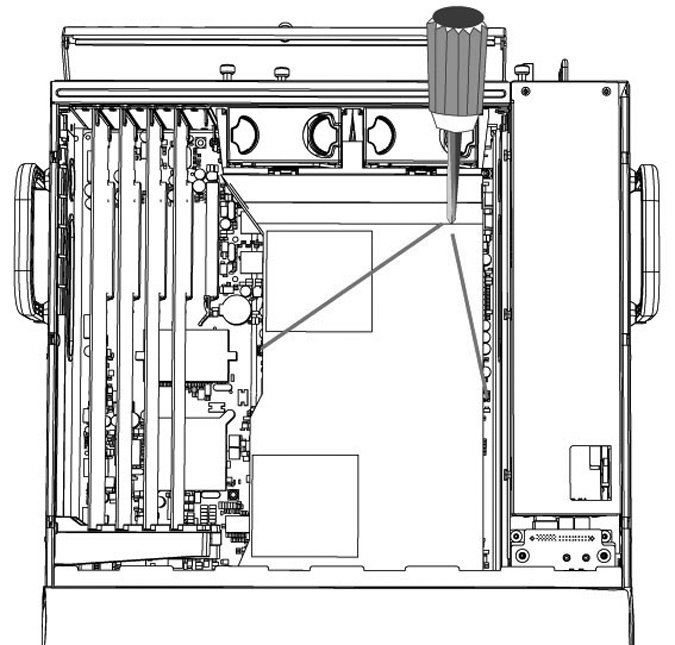
1. Using a magnetic Phillips screwdriver, remove the two screws securing the cooling shroud to the motherboard.
Figure: Removing the Securing Screws
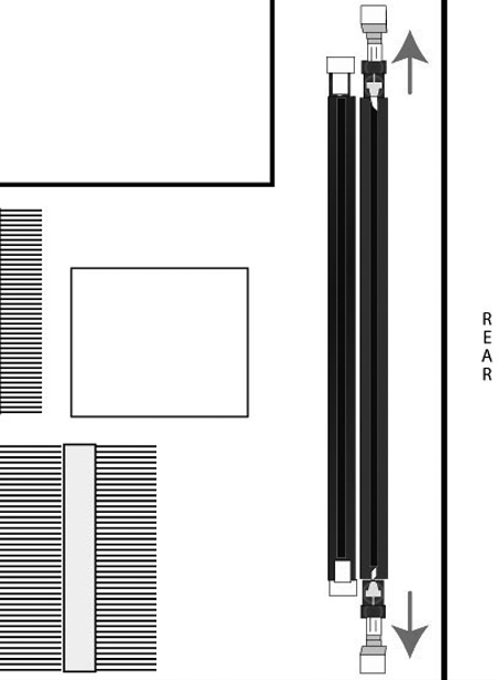
2. Loosen the motherboard locking screw at the back of the chassis and pull the motherboard handle downward and slide the motherboard out 1 to 2 inches from the chassis to release the cooling shroud. Lift the cooling shroud straight up and out of the appliance.
Caution: Be careful not to damage any surrounding components when removing and installing the cooling shroud. Lift the shroud straight up to avoid damaging any components of the shroud.
Figure: Sliding the Motherboard Outward
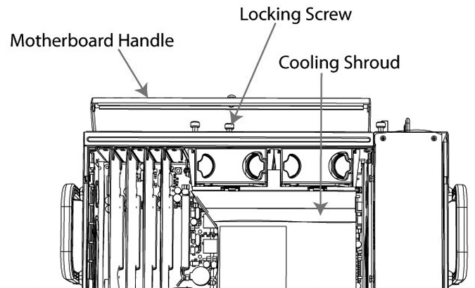
to Release the Cooling Shroud
To replace the memory modules
1. Press the ejector tabs on the memory module slot down and outward and gently pull the memory module out of the slot.
Figure: Accessing the Memory Modules
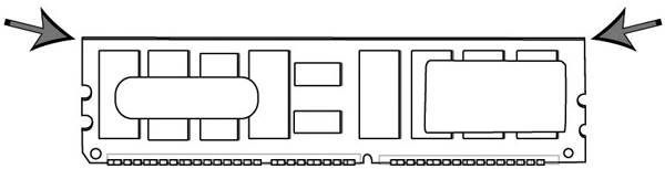
2. Hold the memory module on the outside edges to prevent damage to the module.
Figure: Proper Handling of the Memory Module
3. Remove the existing memory module and replace it with an approved memory module of the same size.
Note: Replacing the existing memory module with a module of a different size causes the system to fail. You must use approved memory modules. Contact Riverbed Support at https://support.riverbed.com to obtain the correct memory modules.
4. Align the memory-module edge connector with the slot alignment keys and insert it into the slot. The module slot has two alignment keys that allow you to install the module in only one direction.
Figure: Inserting the Memory Modules into the Connector Slot and Securing
5. Press down on the memory module with your thumbs while pulling up on the ejectors with your index fingers to lock the module into the slot.
6. Ensure that all ejector tabs are in the upright locked position.
7. Repeat Steps 3 to Step 7 of this procedure to install the remaining memory modules.
8. Replace the chassis cover.