Simple QoS Configuration
This chapter shows how to quickly configure QoS for a stand-alone site on a SteelHead running RiOS 9.x. It includes this task:
Configuring QoS with a single site
In this example, the stand-alone site is the SteelHead you’re configuring. It has two WAN links:
• inpath0_0 = 20 Mbps
• inpath1_0 = 10 Mbps
The goal of this QoS configuration is to reserve 10% of the WAN bandwidth for VoIP traffic on each link.
Note: If you don’t define the bandwidth for an uplink the default bandwidth configured on the in-path interface is used, which is 1 Gbps and can lead to unwanted results with QoS.
To achieve this goal, you’ll define two classes:
• VoIP class - Guarantees 10% of link bandwidth and contains VoIP RTP-Audio traffic.
• Default class - Handles all remaining traffic that has no guaranteed bandwidth.
First you define the local site parameters, which specify the in-path interfaces bandwidth speed. The local site is the SteelHead you’re configuring.
To define local site parameters
1. Choose the Networking > Network Services: Quality of Service to display the Quality of Service page.
Note: For RiOS release earlier than 9.5, choose the Networking > Topology: Sites & Networks > Sites page. RiOS versions 9.5 and later have this field on both pages.
2. Under Local Site Uplink Bandwidth, click the arrow next to the inpath0_0 uplink to expand it.
3. In the Uplinks pane, complete these fields:
– Bandwidth Down: Type 2000000.
– Bandwidth Up: Type 2000000.
Figure: Configuring the local site
4. Click Save.
Next you define the QoS profile. A QoS profile is simply a collection of QoS classes and associated rules. A QoS profile can be associated with traffic going to each remote location or site. In this example, the name of the profile is Branch.
To create a new QoS profile
1. Choose Networking > Networking Services: Quality of Service, and click Add QoS Profiles to display the New Profile pop-up window.
Figure: Defining the QoS branch profile
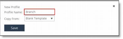
2. Type Branch in the Profile Name text box, and click Save.
3. Under QoS Profiles, click Edit for the Branch profile to display the QoS Profile Details page.
4. Under QoS Classes, click Edit to display the QoS Classes pane.
5. Click the + add class box to display the New Class pop-up window.
Figure: The + Add Class box
6. To create the VoIP class with 10% maximum bandwidth and a priority of Real Time, complete these fields:
– Class Name: Type VoIP.
– Minimum Bandwidth: Type 10.
Figure: Creating the VoIP class in the branch profile
7. Click Add Class to display the new class in the QoS Classes hierarchy.
Next you create the Default class. The Default class ensures that all the remaining traffic will have a Real Time priority after the VoIP traffic bandwidth has been allocated.
To define the Default class
1. Click the + add class box directly below the VoIP class that you just created. This selection creates a class at the same hierarchical level as the VoIP class.
Figure: Adding the Default class to the hierarchy
2. In the New Class pop-up window, complete these fields:
– Class Name: Type Default.
– Minimum Bandwidth: Type 1.
– Priority: Select 4 from the drop-down list, which corresponds to normal traffic. This setting ensures that the VoIP traffic will have a higher priority than the default traffic.
Figure: Creating the Default class
3. Click Add Class and then click Save to save the Default class. The new classes appear in the QoS Rules list.
After you’ve defined the classes, you define the rules for them. QoS rules are defined in the same page as QoS classes, which is the QoS Profile Details page.
To define QoS rules
1. To define QoS rules, click Add a Rule, type RTP- in the Application text box and select RTP-Audio from the Application Flow Engine (AFE) for the VoIP class traffic.
Figure: Adding the VoIP rule
2. To finish defining the RTP-Audio rule, complete these fields:
– QoS Class: Select VoIP from the drop-down list.
– Outbound DSCP: Select 46 (EF) from the drop-down list to mark the traffic with DSCP.
Figure: Completing the RTP-Audio rule
3. Click Save to display the RTP-Audio rule in the QoS rules table.
4. To point the Any rule to the Default class created earlier, click the arrow (>) next to the Any name to expand the page.
Figure: Pointing the Any rule to the Default class
5. Select Default from the QoS Class drop-down list, and click Save.
The Default rule matches all the remaining traffic to the Default class.
Figure: Any rule matches all the remaining traffic to the Default class

Now you need to associate the QoS profile with a site. The SteelHead ships with two site definitions:
• Local - This is the SteelHead you're configuring.
• DefaultSite - Matches the outbound traffic to all remote destinations (0.0.0.0/0). (If a specific QoS profile is required for traffic destined to a specific location, define a new site and specify the IP subnets of the remote site.)
In this example, you associate the QoS profile with the Default site.
To edit the Default site
1. Choose Networking > Topology: Sites & Networks to display the Sites & Networks page.
2. Under Sites, click Edit Site for the DefaultSite site to display the Edit an Existing Site pop-up window.
Figure: Editing the Default site
3. To associate the outbound traffic with the Branch profile in the Default Site, under QoS Profiles select Branch from the Outbound QoS Profiles drop-down list, and click Save.
Figure: Associated branch profile to Default site
The final task is to enable QoS shaping and marking.
To enable QoS shaping and marking
1. Choose Networking > Networking Services: Quality of Service to display the Quality of Service page.
2. Select Enable Outbound QoS Shaping and Enable Outbound QoS Marking, and click Save.
Figure: Enabling QoS shaping and marking
Configuration notes
• Duplicate subnet definitions aren’t allowed.
• The longest match for a subnet definition takes priority. For example, if Site A has subnet 10.0.0.0/16 and Site B has subnet 10.0.0.0/24, then traffic to 10.0.0.1 will be classified under Site B.
• The bandwidth and latency allocations are applied across all the interfaces. If you allocate 10% of the bandwidth for VoIP traffic, then that would be 10% of the 20 Mbps link and 10% of the 10 Mbps link.