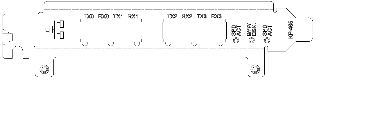
Figure: Four-Port Copper Bypass (Type 1) NIC-1-001G-4TX-BP 
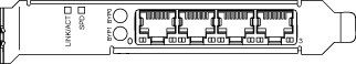
Port | Description |
L0, W0, L1, W1 | Provides access to 10/100/1000 Base-T |
LED | Type 1 definitions | Type 2 definitions |
LINK/ACT | Link = Green Activity = Blinking green | Link = Green Activity = Blinking green |
BYP/DISC. SPD | 1000Mbit/s = Yellow 100Mbit/s = Green 10Mbit/s = Off Bypass = Blinks green Disconnect = Blinks yellow | N/A |
SPD | N/A | 1000Mbit/s = Orange 100Mbit/s = Green 10Mbit/s = Off |
BYP1, BYP0 | N/A | Disconnect = Yellow Bypass = Green Normal: Off |
Specification | Descriptions |
Connectors | Four shielded RJ-45 |
Cables and operating distance | 10Base - T Category 3, 4, or 5 maximum 50m * 100Base - TX Category 5 maximum 50m * 1000Base - T Category 5E maximum 50m * *Theoretical distance is defined as half a distance as stated by the IEEE 802.3 standard. |
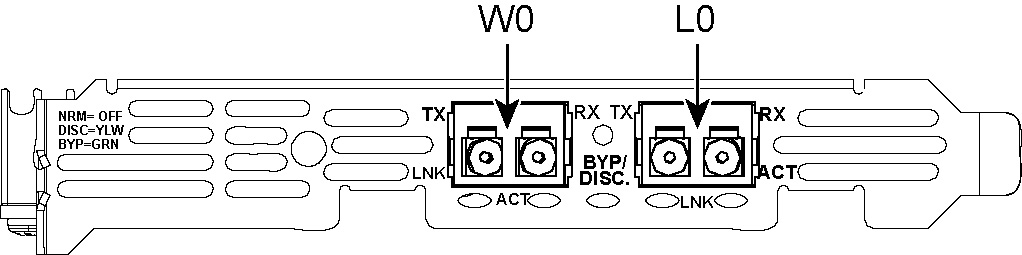
 Two-Port 1-GbE Fiber SX (Type 1) NIC-1-001G-2SX-BP
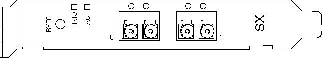
Port | Description |
P0, P1 | TX and RX provides access to 1000 Base-SX |
LED | Type 1 definition | Type 2 definition |
ACT | Activity = Blinks green | Activity = Blinks yellow |
BYP/DSC. | Normal = Off Disconnect = Yellow Bypass = Green | Normal = Off Disconnect = Red Bypass = Green |
LNK | Link = Yellow | Link: Green No link: Off |
Specification | Description |
Connectors | Two small form factor (SFF) LC fiber connectors |
Cables and operating distance | Multimode fiber = 137 m maximum at 62.5 um cable (half of theoretical distance of IEEE 802.3 standard) |
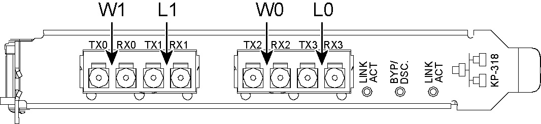
 Four-Port 1-GbE Fiber SX (Type 1) NIC-1-001G-4SX-BP
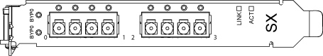
Port | Description |
L0, W0, L1, W1 | TX and RX provides access to 1000 Base-SX |
LED | Type 1 definitions | Type 2 definitions |
LNK | N/A | Link = Green |
LNK/ACT | Link = Green Activity = Blinks green | N/A |
BYP/DSC | Normal = Off Disconnect = Yellow Bypass = Green | Normal = Off Disconnect = Yellow Bypass = Green |
ACT | N/A | On = Blinking orange |
Specification | Definition |
Connectors | 4 small form factor (SFF) LC fiber connectors |
Cables and operating distance | Multimode fiber = 137 m maximum at 62.5 um cable (half of theoretical distance of IEEE 802.3 standard) |
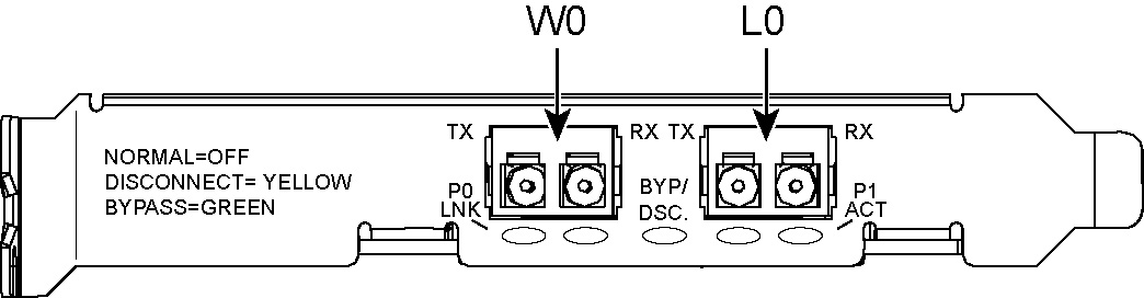
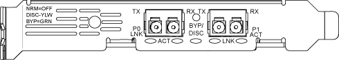
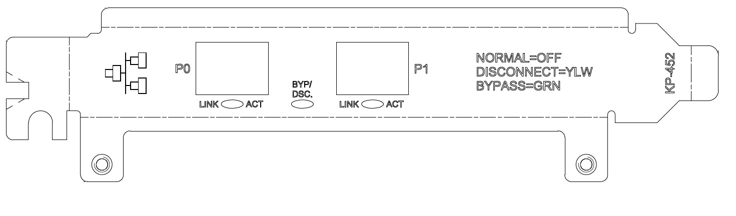
Port | Description |
P0, P1 | TX and RX provides access to 1000 Base-LX |
LED | Definition |
P0 ACT, P1 ACT | Activity status of the port |
LNK | Link = Yellow |
ACT | Activity = Blinks green |
BYP/DSC | Normal = Off Disconnect = Yellow Bypass = Green |
Specification | Description |
Connectors | Two small form factor (SFF) LC fiber connectors |
Cables and Operating distance | Single-mode fiber: 9 um 2500 m maximum at 9 um* * Theoretical distance is defined as half a distance as stated by the IEEE 802.3 standard. |
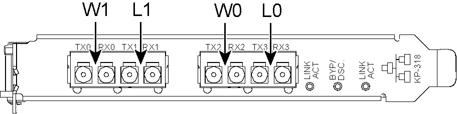
Port | Description |
L0, W0, L1, W1 | TX and RX provides access to 1000 Base-LX |
LED | Definition |
LINK/ACT | Link = Green Activity = Blinks green |
BYP/DSC | Normal = Off Disconnect = Yellow Bypass = Green |
Specifications | Description |
Connectors | Four small form factor (SFF) LC fiber connectors |
Cables and operating distance | Single-mode fiber: 9 um 2500 m maximum at 9 um* * Theoretical distance is defined as half a distance as stated by the IEEE 802.3 standard. |
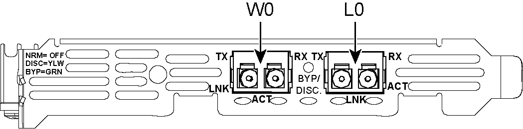
Port | Description |
L0, W0 | TX and RX provides access to 10GBase-SR |
LED | Definition |
LNK | Link = Yellow |
ACT | Activity = Blinks green |
BYP/DSC | Normal = Off Disconnect = Yellow Bypass = Green |
Specification | Definition |
Connectors | Two small form factor (SFF) LC fiber connectors |
Cables and operating distance | Multimode fiber: 13 m using 62.5 um, 160 MHz*km 16.5 m using 62.5 um, (OM1) 200 MHz*km 33 m using 50 um, 400 MHz*km 41 m using 50 um, (OM2) 500 MHz*km 150m using 50 um, (OM3) 2000 MHz*km All distances are the theoretical distance, which is defined as half a distance as specified in the optical transceiver. |
Port | Description |
L0, W0 | TX and RX provides access to 10GBase-LR |
LED | Definition |
LNK | Link = Yellow |
ACT | Activity = Blinks green |
BYP/DSC | Normal = Off Disconnect = Yellow Bypass = Green |
Specification | Definition |
Connectors | Two small form factor (SFF) LC fiber connectors |
Cables and operating distance | Single-mode fiber: 9 u, Max 5 km * * Theoretical distance is defined as half a distance as specified in the optical transceiver. |
Port | Description |
P0, P1 | P0 and P1 provide access to 40GBase-SR |
LED | Definition |
LINK/Activity | Link = Green Activity = Blinks green |
BYP/DSC | Normal = Off Disconnect = Yellow Bypass = Green |
Specification | Definition |
Connectors | Four small form factor MTP-MTP fiber connectors |
Cables and operating distance | Multimode Fiber 0.5 to 50m using 50um, (OM3) 1500 MHz*Km 0.5 to 75m using 50um, (OM4) 3500 MHz*Km** ** All distances are defined as half a distance as specified in the optical transceiver. |
Port | Description |
P0, P1 | P0 and P1 provide access to 40GBase-LR4 |
LED | Definition |
LINK/Activity | Link = Green Activity = Blinks green |
BYP/DSC | Normal = Off Disconnect = Yellow Bypass = Green |
Specification | Definition |
Connectors | Four small form factor (SFF) LC fiber connectors |
Cables and operating distance | 5km using SMF-28 cables Distance is defined as half of the distance as specified in the optical transceiver. |
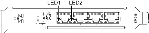
Port | Description |
P0, P1, P2, P3 | Provides access to 10/100/1000 Base-TX |
LED | Description |
Link/Activity (LED1) | Link: Green |
Activity: Blinking green | |
Speed (LED2) | 1 G: Yellow |
100 M: Green | |
10 M: Off |
Connectors | Four shielded RJ-45 |
Cables and operating distance | 10 Base-T Category 3, 4, or 5 maximum 100 m 100 Base-TX Category 5 maximum 100 m 1000 Base-T Category 5E maximum 100 m |
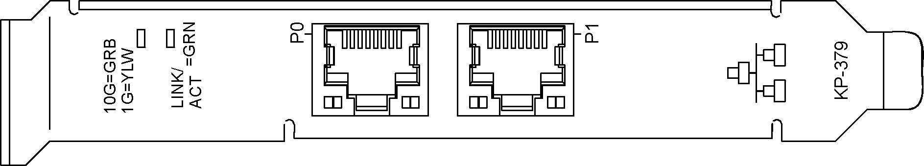
Port | Description |
P0, P1 | Provides access to 100/1000/10G Base-T |
LED | Description |
10G=GRN 1G=YLW (LED1) | 10 G = Green 1 G = Yellow 100 M = Off |
LINK/ACT=GRN (LED2) | Link = Green Activity = Blinking green |
Specification | Description |
Connectors | Two shielded RJ-45 |
Cables and operating distance | 100Base-TX Category 5 maximum 100m 1000Base-T Category 5E maximum 100m 10GBase-T Category 6A maximum 100m |
Port | Description |
P0, P1, P2, P3 | Provides access to 100/1000/10G Base-T |
LED | Description |
10G=GRN 1G=YLW (LED1) | 10 G = Green 1 G = Yellow 100 M = Off |
LINK/ACT=GRN (LED2) | Link = Green Activity = Blinking green |
Specification | Description |
Connectors | Four shielded RJ-45 |
Cables and operating distance | 100Base-TX Category 5 maximum 100m 1000Base-T Category 5E maximum 100m 10GBase-T Category 6A maximum 100m |
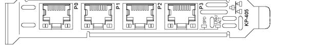
Port | Description |
P0, P1, P2, P3 | Provides access to 1000 Base-TX, LX, or SX |
LED | Description |
LNK | Yellow |
LNK/ACT | Link Green Activity: Blinking green |
Specification | Description |
Connectors | Four small form factor pluggable (SFP) cage |
Cables and operating distances | |
SFP 1GBase-Copper module | 1000 Base-T Category 5E maximum 100 m |
SFP 1GBase-SX module | Multimode Fiber: 220 m using 62.5 um 550 m using 50 um |
SFP 1GBase-LX module | Single-mode Fiber: 5000 m using 9 um Multimode Fiber: 550 m using 50 um 550 m using 62.5 um |
Supported SFPs | Manufacturing part # | Orderable part # |
SFP 1 GbE Copper module | 410-00138-01 | TRC-1-SFP-TX-C |
SFP 1 GbE SX | 410-00139-01 | TRC-1-SFP-SX |
SFP 1 GbE LX | 410-00140-01 | TRC-1-SFP-LX |
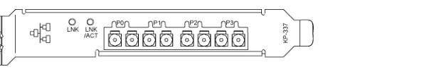
Port | Description |
P0, P1, P2, P3 | Provides access to 10G Base-SR, LR, or DAC |
LED | Description |
LNK P0, LNK P1 | Green |
LNK/ACT | Link= Green Activity = Blinking green |
Specification | Description |
Connectors | Two small form factor pluggable (SFP+) cage |
Cables and operating distance for the supported SFPs | |
SFP+ 10 GbE Direct Attached Cable | 10-G Passive Direct Attach Cable, up to 10 meters |
SFP+ 10GBase-SR module 62.5 um | 160 MHz/km 26 m 62.5 um, (OM1) 200 MHz/km 33 m 50 um, 400 MHz/km 66 m 50 um, (OM2) 500 MHz/km 82m 50 um, (OM3) 2000 MHz/km 300m |
SFP+ 10GBase-LR module | Single-Mode = 10000 m at 9 um |
SFPs | Manufacturing part # | Orderable part # |
SFP+ 10 GbE DAC | 410-00140-01 | TRC-1-SFPP-DAC-C |
SFP+ 10 GbE SR | 410-00143-01 | TRC-1-SFPP-SR |
SFP+ 10 GbE LR | 410-00144-01 | TRC-1-SFPP-LR |
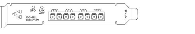
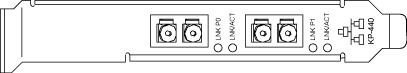
Port | Description |
P0, P1, P2, P3 | Provides access to 10G Base-SR, LR, or DAC |
LED | Description |
Speed | Blue = 10 G Yellow = 1 G |
Link/Activity | Link = Green Activity = Blinking |
Specification | Description |
Connectors | Two small form factor pluggable (SFP+) cage |
Cables and operating distance for the supported SFPs | |
SFP+ 10 GbE Direct Attached Cable | 10-G Passive Direct Attach Cable, up to 10 meters |
SFP+ 10GBase-SR module 62.5 um | 160 MHz/km 26 m 62.5 um, (OM1) 200 MHz/km 33 m 50 um, 400 MHz/km 66 m 50 um, (OM2) 500 MHz/km 82m 50 um, (OM3) 2000 MHz/km 300m |
SFP+ 10GBase-LR module | Single-Mode: 10000 m at 9 um |
SFPs | Manufacturing part # | Orderable part # |
SFP+ 10 GbE DAC | 410-00140-01 | TRC-1-SFPP-DAC-C |
SFP+ 10-GbE SR | 410-00143-01 | TRC-1-SFPP-SR |
SFP+ 10-GbE LR | 410-00144-01 | TRC-1-SFPP-LR |
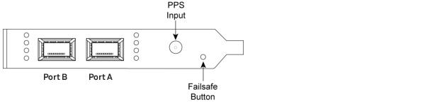
Network Interface | Description |
IEEE standardP0, P1 | IEEE 802.3 40 Gbit/s Ethernet |
Ports P0, P1 | 40Gb/s QSFP+ Interfaces |
Data Rate | 2 x 40 Gbit/s |
Supported QSFP+ modules | 40GBASE-SR4 (850 nm) 40GBASE-LR4 (1310 nm) |
Host Interface | Description |
Physical bus connector | 8-lane PCIe |
PCIe bus type | 1-8 lane PCIe Gen1/Gen2/Gen3 |
PCIe compliant | 64 logical channels that can be connected to DMA or egressed to physical output ports. |
LED | Description |
Link/Activity | Link = Green Activity = Orange Panic = Red |
Fail Safe | Press and hold on power on to load fallback firmware image. |
Specification | Description |
On Board Memory | 8 GB (2x4GB 64 bit DDR3) |
Timestamp Sync | 1pps connector located on printed circuit board, and connected to bracket with cable. |
PCIe | Gen 3, 8 lanes |
Performance | Description |
Capture rate (card internal) | Full line rate |
Capture rate (bursts) | Full line rate |
Capture rate (sustained) | 55 Gbps |
Transmission rate (inline host DMA) | 40 Gbps |
Transmission rate (inline bypass) | 68 Gbps |
Transmission rate (daisy chain) | Full line rate |
Latency | Less than 3 μs to host memory Less than 3 μs from host memory to Tx Non-blocking sending, allowing user applications to operate independently. |
Time Stamping & Sync | Resolution of 3.2 ns Accuracy down to 20 ns Optional external synchronization via PPS Customization for PTP IEEE 1588-2008 RJ45 Master/slave time sync between multiple cards |
Configuration | Dual boot images with automatic fallback to fail-safe image Full firmware upgrades via supplied tools or fbCAPTURE API |
NIC | Size | Manufacturing part # | Orderable part # |
Two-Port 40GbE Time Stamp Card | HHHL | 410-00214-01 | NIC-1-040G-2QSFP-TS |
QSFPs | Manufacturing part # | Orderable part # |
Two-Port 40-GbE PCIe SR4 | 410-00147-01 | TRC-1-QSFP-SR4 |
Two-Port 40-GbE PCIe LR4 | 410-00148-01 | TRC-1-QSFP-LR4 |
Port | Description |
P0, P1, P2, P3 | P0, P1, P2, P3 provide access to 10GBase-SR |
LED | Definition |
LINK/Activity | Link = Yellow on 1GB Link = Green on 10 GB Activity = Blinks green |
BYP/DSC | Normal = Off Disconnect = Yellow Bypass = Green |
Specification | Definition |
Connectors | Four small form factor MTP-MTP fiber connectors |
Cables and operating distance | Multimode fiber 13m using 62.5um, 160MHz/Km 16.5m using 62.5um, (OM1)200MHz/Km 33m using 50um, 400MHz/Km 41m using 50um, (OM2)500 MHz/Km 150m using 50um, (OM3)2000MHz/Km All distances are defined as half a distance as specified in the optical transceiver. |
Port | Description |
P0, P1 | P0, P1, P2, and P3 provide access to 10GBase-LR4 |
LED | Definition |
LINK/Activity | Link = Yellow on 1GB Link = Green on 10 GB Activity = Blinks green |
BYP/DSC | Normal = Off Disconnect = Yellow Bypass = Green |
Specification | Definition |
Connectors | Four small form factor (SFF) LC fiber connectors |
Cables and operating distance | Singlemode fiber 5 km using 9u All distances are defined as half a distance as specified in the optical transceiver. |