Deploying the Core
This chapter describes the deployment processes specific to the Core. It includes the following sections:
Core dashboard overview
Although not actually a deployment process, a SteelFusion Core running software version 4.3 or later has a dashboard that, when the Core is initially deployed, provides widgets that direct the administrator to key configuration tasks such as the ones covered in the following sections. Therefore, it is very easy to see at a glance which deployment tasks have not yet been completed. Widgets are provided for adding an Edge, adding a failover peer, adding a storage array, and adding LUNs. Once configuration is complete, the dashboard provides a graphical view of SteelFusion-related activity (cache efficiency, Edge read/write performance), status reports (Core alarms, HA health), and storage (LUN capacity, backend storage performance).
For details on the Core dashboard, see the SteelFusion Core Management Console User’s Guide.
Core deployment process overview
Complete the following tasks:
1. Install and connect the Core in the data center network.
Include both Cores if you are deploying a high-availability solution. For more information on installation, see the SteelFusion Core Installation and Configuration Guide.
2. Configure the iSCSI initiators in the Core using the iSCSI Qualified Name (IQN) format.
3. Enable and provision LUNs on the storage array.
4. Define the Edge identifiers so you can later establish connections between the Core and the corresponding Edges.
Interface and port configuration
This section describes a typical port configuration. You might require additional routing configuration depending on your deployment scenario.
This section includes the following topics:
Core ports
The following table summarizes the ports that connect the Core appliance to your network. Unless noted, the port and descriptions are for all Core models: 2000, 3000, and 3500.
Port | Description |
Console | Connects the serial cable to a terminal device. You establish a serial connection to a terminal emulation program for console access to the Setup Wizard and the Core CLI. |
Primary
(PRI) | Connects Core to a VLAN switch through which you can connect to the Management Console and the Core CLI. You typically use this port for communication with Edges. |
Auxiliary (AUX) | Connects the Core to the management VLAN. You can connect a computer directly to the appliance with a crossover cable, enabling you to access the CLI or Management Console. |
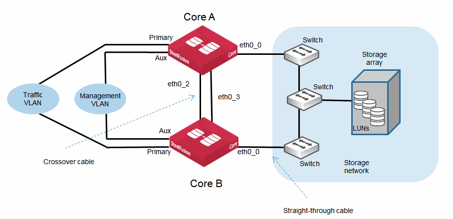
eth0_0 to eth0_3 Applies to SFCR 2000 and 3000 | Connects the eth0_0, eth0_1, eth0_2, and eth0_3 ports of Core to a LAN switch using a straight-through cable. You can use the ports either for iSCSI SAN connectivity or failover interfaces when you configure Core for high availability (HA) with another Core. In an HA deployment, failover interfaces are usually connected directly between Core peers using crossover cables. If you deploy the Core between two switches, all ports must be connected with straight-through cables. |
eth1_0 onwards Applies to SFCR 2000 and 3000 | Cores have four gigabit Ethernet ports (eth0_0 to eth0_3) by default. For additional connectivity, you can install optional NICs in PCIe slots within the Core. These slots are numbered 1 to 5. Supported NICs can be either 1 Gb or 10 Gb depending on connectivity requirements. The NIC ports are automatically recognized by the Core, following a reboot. The ports are identified by the system as ethX_Y where X corresponds to the PCIe slot number and Y corresponds to the port on the NIC. For example, a two-port NIC in PCIe slot 1 is displayed as having ports eth1_0 and eth1_1. Connect the ports to LAN switches or other devices using the same principles as the other SteelFusion network ports. For more details about installing optional NICs, see the Network and Storage Card Installation Guide. For more information about the configuration of network ports, see the SteelFusion Core Management Console User’s Guide. |
eth1_0 to eth1_3 Applies to SRCR 3500 | Connects the eth1_0, eth1_1, eth1_2, and eth1_3 ports of Core to a LAN switch using a straight-through cable. You can use the ports either for iSCSI SAN connectivity or failover interfaces when you configure Core for high availability (HA) with another Core. In an HA deployment, failover interfaces are usually connected directly between Core peers using crossover cables. If you deploy the Core between two switches, all ports must be connected with straight-through cables. |
eth2_0 onwards Applies to SRCR 3500 | Cores have four gigabit Ethernet ports (eth1_0 to eth1_3) by default. For additional connectivity, you can install optional NICs in PCIe slots within the Core. These slots are numbered 2 to 6. Supported NICs can be either 1 Gb or 10 Gb depending on connectivity requirements. The NIC ports are automatically recognized by the Core, following a reboot. The ports are identified by the system as ethX_Y where X corresponds to the PCIe slot number and Y corresponds to the port on the NIC. For example, a two-port NIC in PCIe slot 2 is displayed as having ports eth2_0 and eth2_1. Connect the ports to LAN switches or other devices using the same principles as the other SteelFusion network ports. For more details about installing optional NICs, see the Network and Storage Card Installation Guide. For more information about the configuration of network ports, see the SteelFusion Core Management Console User’s Guide. |
Figure: Core Ports for Core models 2000 and 3000 shows a basic HA deployment indicating some of the SFCR 2000 and 3000 ports and use of straight-through or crossover cables. You can use the same deployment and interface connections for the 3500, but the interface names are different.
Figure: Core Ports for Core models 2000 and 3000
Configuring interface routing
You configure interface routing by choosing Configure > Networking: Management Interfaces from the Core Management Console.
Note: If all the interfaces have different IP addresses, you do not need additional routes.
This section describes the following scenarios:
All interfaces have separate subnet IP addresses
In this scenario, you do not need additional routes.
The following table shows a sample configuration in which each interface has an IP address on a separate subnet.
Interface | Sample configuration | Description |
Auxiliary | 192.168.10.2/24 | Management (and default) interface. |
Primary | 192.168.20.2/24 | Interface to WAN traffic. |
eth0_0 | 10.12.5.12/16 | Interface for storage array traffic. |
eth0_1 | | Optional, additional interface for storage array traffic. |
eth0_2 | 192.168.30.2/24 | HA failover peer interface, number 1. |
eth0_3 | 192.168.40.2/24 | HA failover peer interface, number 2. |
All interfaces are on the same subnets
If all interfaces are in the same subnet, only the primary interface has a route added by default. You must configure routing for the additional interfaces.
The following table shows a sample configuration.
Interface | Sample configuration | Description |
Auxiliary | 192.168.10.1/24 | Management (and default) interface. |
Primary | 192.168.10.2/24 | Interface to WAN traffic. |
eth0_0 | 192.168.10.3/24 | Interface for storage array traffic. |
To configure additional routes
1. In the Core Management Console, choose Configure > Networking: Management Interfaces.
Figure: Routing Table on the management interfaces page
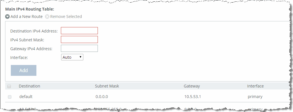
2. Under Main IPv4 Routing Table, use the following controls to configure routing as necessary.
Control | Description |
Add a New Route | Displays the controls for adding a new route. |
Destination IPv4 Address | Specify the destination IP address for the out-of-path appliance or network management device. |
IPv4 Subnet Mask | Specify the subnet mask. For example, 255.255.255.0. |
Gateway IPv4 Address | Optionally, specify the IP address for the gateway. |
Interface | From the drop-down list, select the interface. |
Add | Adds the route to the table list. |
3. Repeat for each interface that requires routing.
4. Click Save to save your changes permanently.
You can also perform this configuration using the ip route CLI command. For details, see the SteelFusion Command-Line Interface Reference Manual.
Some interfaces, except primary, share the same subnets
If a subset of interfaces, excluding primary, are in the same subnet, you must configure additional routes for those interfaces.
The following table shows a sample configuration.
Interface | Sample Configuration | Description |
Auxiliary | 10.10.10.1/24 | Management (and default) interface. |
Primary | 10.10.20.2/24 | Interface to WAN traffic. |
eth0_0 | 192.168.10.3/24 | Interface for storage array traffic. |
eth0_1 | 192.168.10.4/24 | Additional interface for storage array traffic. |
To configure additional routes
1. In the Core Management Console, choose Configure > Networking: Management Interfaces.
2. Under Main IPv4 Routing Table, use the following controls to configure routing as necessary.
Control | Description |
Add a New Route | Displays the controls for adding a new route. |
Destination IPv4 Address | Specify the destination IP address for the out-of-path appliance or network management device. |
IPv4 Subnet Mask | Specify the subnet mask. For example, 255.255.255.0. |
Gateway IPv4 Address | Optionally, specify the IP address for the gateway. |
Interface | From the drop-down list, select the interface. |
Add | Adds the route to the table list. |
3. Repeat for each interface that requires routing.
4. Click Save to save your changes permanently.
You can also perform this configuration using the ip route CLI command. For details, see the SteelFusion Command-Line Interface Reference Manual.
Some interfaces, including primary, share the same subnets
If some but not all interfaces, including primary, are in the same subnet, you must configure additional routes for those interfaces.
The following table shows a sample configuration.
Interface | Sample Configuration | Description |
Aux | 10.10.10.2/24 | Management (and default) interface. |
Primary | 192.168.10.2/24 | Interface to WAN traffic. |
eth0_0 | 192.168.10.3/24 | Interface for storage array traffic. |
eth0_1 | 192.168.10.4/24 | Additional interface for storage array traffic. |
eth0_2 | 20.20.20.2/24 | HA failover peer interface, number 1. |
eth0_3 | 30.30.30.2/24 | HA failover peer interface, number 2. |
To configure additional routes
1. In the Core Management Console, choose Configure > Networking: Management Interfaces.
2. Under Main IPv4 Routing Table, use the following controls to configure routing as necessary.
Control | Description |
Add a New Route | Displays the controls for adding a new route. |
Destination IPv4 Address | Specify the destination IP address for the out-of-path appliance or network management device. |
IPv4 Subnet Mask | Specify the subnet mask. For example, 255.255.255.0. |
Gateway IPv4 Address | Optionally, specify the IP address for the gateway. |
Interface | From the drop-down list, select the interface. |
Add | Adds the route to the table list. |
3. Repeat for each interface that requires routing.
4. Click Save to save your changes permanently.
You can also perform this configuration using the ip route CLI command. For details, see the SteelFusion Command-Line Interface Reference Manual.
Configuring Core for jumbo frames
If your network infrastructure supports jumbo frames, configure the connection between the Core and the storage system as described in this section. Depending on how you configure Core, you might configure the primary interface or one or more data interfaces.
In addition to configuring Core for jumbo frames, you must configure the storage system and any switches, routers, or other network devices between Core and the storage system.
To configure Core for jumbo frames
1. In the Core Management Console, choose Configure > Networking and open the relevant page (Management Interfaces or Data Interfaces) for the interface used by the Core to connect to the storage network. For example, eth0_0.
2. On the interface on which you want to enable jumbo frames:
– Enable the interface.
– Select the Specify IPv4 Address Manually option and enter the correct value for your implementation.
– Specify 9000 bytes for the MTU setting.
3. Click Apply to apply the settings to the current configuration.
4. Click Save to save your changes permanently.
To configure jumbo frames on you storage array, see the documentation from your storage array vendor.
Configuring the iSCSI initiator
The iSCSI initiator settings dictate how the Core communicates with one or more storage arrays through the specified portal configuration.
iSCSI configuration includes:
• Initiator name
• Enabling header or data digests (optional)
• Enabling CHAP authorization (optional)
• Enabling MPIO and standard routing for MPIO (optional)
CHAP functionality and MPIO functionality are described separately in this document. For more information, see
Using CHAP to secure iSCSI connectivity and
Use CHAP.
In the Core Management Console, you can view and configure the iSCSI initiator, local interfaces for MPIO, portals, and targets by choosing Configure > Storage: iSCSI, Initiators, MPIO. For more information, see the SteelFusion Core Management Console User’s Guide.
In the Core CLI, use the following commands to access and manage iSCSI initiator settings:
• storage lun modify auth-initiator to add or remove an authorized iSCSI initiator to or from the LUN
• storage iscsi data-digest to include or exclude the data digest in the iSCSI (PDU)
• storage iscsi header-digest to include or exclude the header digest in the iSCSI PDU
• storage iscsi initiator to access numerous iSCSI configuration settings
Configuring LUNs
This section includes the following topics:
Before you can configure LUNs in Core, you must provision the LUNs on the storage array and configure the iSCSI initiator. For more information, see
Provisioning LUNs on the storage array and
Configuring the iSCSI initiator.
Exposing LUNs
You expose LUNs by scanning for LUNs on the storage array, and then mapping them to the Edges. After exposing LUNs, you can further configure them for failover, MPIO, snapshots, and pinning and prepopulation.
In the Core Management Console, you can expose and configure LUNs by choosing Configure > Manage: LUNs. For more information, see the SteelFusion Core Management Console User’s Guide.
In the Core CLI, you can expose and configure LUNs with the following commands:
• storage iscsi portal host rescan-luns to discover available LUNs on the storage array
• storage lun add to add a specific LUN
• storage lun modify to modify an existing LUN configuration
For more information, see the SteelFusion Command-Line Interface Reference Manual.
Resizing LUNs
Granite 2.6 introduced the LUN expansion feature. Prior to Granite 2.6, to resize a LUN you needed to unmap the LUN from an Edge, remove the LUN from Core, change the size on the storage array, add it back to Core, and map it to the Edge.
The LUN expansion feature generally automatically detects LUN size increases made on a data center storage array if there are active read and write operations, and then propagates the change to the Edge. However, if there are no active read and write operations, you must perform a LUN rescan on the Core Configure > Manage: LUNs page for the Core to detect the new LUN size.
If the LUN is pinned, you need to make sure the blockstore on its Edge can accommodate the new size of the LUN.
Note: If you have configured SteelFusion Replication, the new LUN size on the primary Core is updated only when the replica LUN size is the same or greater.
Configuring Fibre Channel LUNs
The process of configuring Fibre Channel LUNs for Core requires configuration in both the ESXi server and the Core.
For more information, see
SteelFusion and Fibre Channel and the
Fibre Channel on SteelFusion Core Virtual Edition Solution Guide.
Removing a LUN from a Core configuration
This section describes the process to remove a LUN from a Core configuration. This process requires actions on both the Core and the server running at the branch.
Note: In the following example procedure, the branch server is assumed to be a Windows server; however, similar steps are required for other types of servers.
To remove a LUN
1. At the branch where the LUN is exposed:
• Power down the local Windows server.
• If the Windows server runs on ESXi, you must also unmount and detach the LUN from ESXi.
2. At the data center, take the LUN offline in the Core configuration.
When you take a LUN offline, outstanding data is flushed to the storage array LUN and the blockstore cache is cleared. The offline procedure can take a few minutes.
Depending on the WAN bandwidth, latency, utilization, and the amount of data in the Edge blockstore that has not yet been synchronized back to the data center, this operation can take seconds to many minutes or even hours. Use the reports on the Edge to help understand just how much data is left to be written back. Until all the data is safely synchronized back to the LUN in the data center, the Core keeps the LUN in an offlining state. Only when the data is safe does the LUN status change to offline.
To take a LUN offline, use one of the following methods:
• CLI - Use the storage lun modify offline command.
• Management Console - Choose Configure > Manage: LUNs to open the LUNs page, select the LUN configuration in the list, and select the Details tab.
3. Remove the LUN configuration using one of the following methods:
• CLI - Use the storage lun remove command.
• Management Console - Choose Configure > Manage: LUNs to open the LUNs page, locate the LUN configuration in the list, and click the trash icon.
For details about CLI commands, see the SteelFusion Command-Line Interface Reference Manual. For details about using the Core Management Console, see the SteelFusion Core Management Console User’s Guide.
Configuring redundant connectivity with MPIO
The MPIO feature enables you to configure multiple physical I/O paths (interfaces) for redundant connectivity with the local network, storage system, and iSCSI initiator.
Both Core and Edge offer MPIO functionality. However, these features are independent of each other and do not affect each other.
MPIO in Core
The MPIO feature enables you to connect Core to the network and to the storage system through multiple physical I/O paths. Redundant connections help prevent loss of connectivity in the event of an interface, switch, cable, or other physical failure.
You can configure MPIO at the following separate and independent points:
• iSCSI initiator - This configuration allows you to enable and configure multiple I/O paths between the Core and the storage system. Optionally, you can enable standard routing if the iSCSI portal is not in the same subnet as the MPIO interfaces.
• iSCSI target - This configuration allows you to configure multiple portals on the Edge. Using these portals, an initiator can establish multiple I/O paths to the Edge.
Configuring Core MPIO interfaces
You can configure MPIO interfaces through the Core Management Console or the Core CLI.
In the Core Management Console, choose Configure > Storage Array: iSCSI, Initiator, MPIO. Configure MPIO using the following controls:
• Enable MPIO.
• Enable standard routing for MPIO. This control is required if the backend iSCSI portal is not in the same subnet of at least two of the MPIO interfaces.
• Add (or remove) local interfaces for the MPIO connections.
For details about configuring MPIO interfaces in the Core Management Console, see the SteelFusion Core Management Console User’s Guide.
In the Core CLI, open the configuration terminal mode and run the following commands:
• storage iscsi session mpio enable to enable the MPIO feature.
• storage iscsi session mpio standard-routes enable to enable standard routing for MPIO. This command is required if the backend iSCSI portal is not in the same subnet of at least two of the MPIO interfaces.
• storage lun modify mpio path to specify a path.
These commands require additional parameters to identify the LUN. For details about configuring MPIO interfaces in the Core CLI, see the SteelFusion Command-Line Interface Reference Manual.
Core pool management
This section describes Core pool management. It includes the following topics:
Overview of Core pool management
Core Pool Management simplifies the administration of large installations in which you need to deploy several Cores. Pool management enables you to manage storage configuration and check storage-related reports on all the Cores from a single Management Console.
Pool management is especially relevant to Core-v deployments when LUNs are provided over Fibre Channel. VMware ESX has a limitation for raw device mapping (RDM) LUNs, which limits Core-v to 60 LUNs. In releases prior to SteelFusion 3.0, to manage 300 LUNs, you needed to deploy five separate
Core-vs. To ease the Core management in SteelFusion 3.0 and later, you can combine Cores into management pools.
In SteelFusion 3.0 and later, you can enable access to the SteelHead REST API framework. This access enables you to generate a REST API access code for use in SteelFusion Core pool management. You can access the REST API by choosing Configure > Pool Management: REST API Access.
For more information about pool management, see SteelFusion Core Management Console User’s Guide.
Pool management architecture
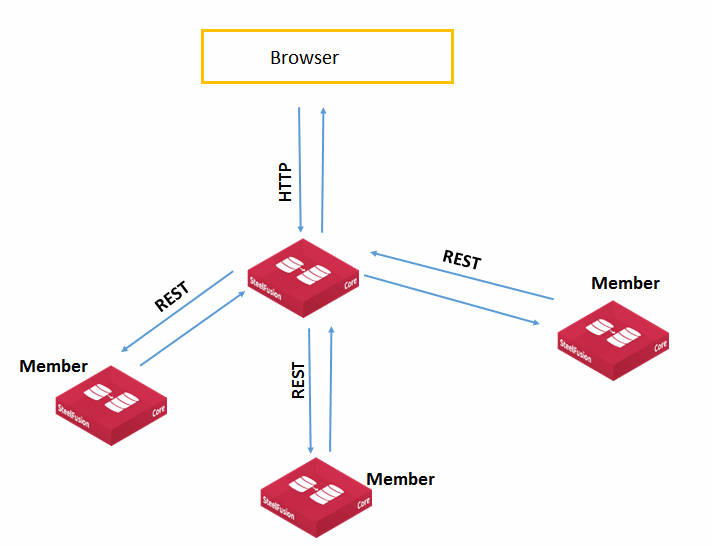
Pool management is a two-tier architecture that allows each Core to become either manager or a member of a pool. A Core can be part of only one pool. The pool is a single-level hierarchy with a flat structure, in which all members of the pool except the manager have equal priority and cannot themselves be managers of pools. The pool has a loose membership, in which pool members are not aware of one another, except for the manager. Any Core can be the manager of the pool, but the pool manager cannot be a member of any other pool. You can have up to 32 Cores in one pool, not including the manager.
The pool is dissolved when the manager is no longer available (unless the manager has an HA peer). Management of a pool can be taken over by a failover peer. However, a member failover peer cannot be managed by the member pool manager through the member, even if the failover peer is down.
From a performance prospective, it does not matter which Core you choose as the manager. The resources required by the pool manager have minor to no differences from regular Core operations.
Figure: Core two-tier pool management
Configuring pool management
This section describes how to configure pool management.
These are the high-level steps:
You can configure pool management only through the Management Console.
To create a pool
1. Decide which Core you want to become the pool manager.
2. In the Management Console of the pool manager, choose Configure > Pool Management: Edit Pool.
3. Specify a name for the pool in the Pool Name field.
4. Click Create Pool.
To generate a REST access code for a member
1. In the Management Console of the pool member, choose Configure > Pool Management: REST API Access.
Figure: REST API access page
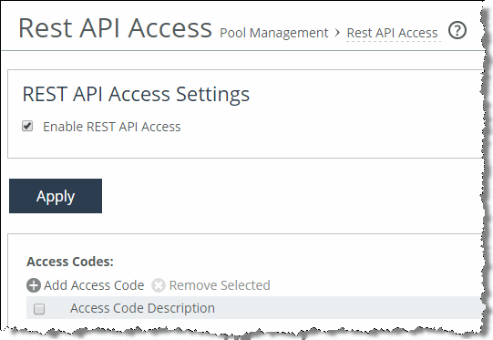
2. Select Enable REST API Access and click Apply.
3. Select Add Access Code.
4. Specify a useful description, such as For Pool Management from <hostname>, in the Description of Use field.
5. Select Generate New Access Code and click Add.
A new code is generated.
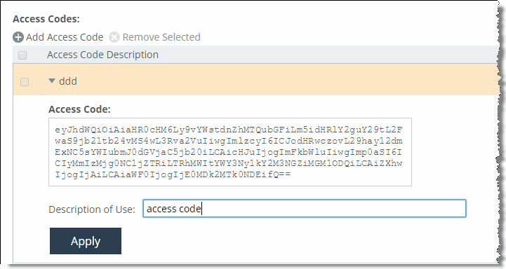
6. Expand the new entry and copy the access code.
Figure: REST API Access code
Note: You can revoke access of a pool manager by removing the access code or disabling REST API access on the member.
Before you begin the next procedure, you need the hostnames or the IP addresses of the Cores you want to add as members.
To add a member to the pool
1. In the Management Console of the pool manager, choose Configure > Pool Management: Edit Pool.
2. Select Add a Pool Member.
3. Add the member by specifying the hostname or the IP address of the member.
4. Paste the REST API access code that you generated in the API Access Code field on the Management Console of the pool member.
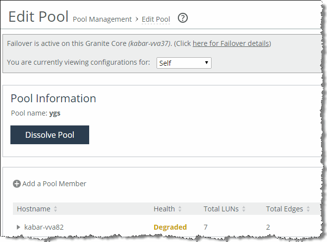
When a member is successfully added to the pool, the pool manager Pool Management page displays statistics about the members, such as health, number of LUNs, model, failover status, and so on.
Figure: Successful pool management configuration
Changing pool management structure
A pool manager can remove individual pool members or dissolve the whole pool. A pool member can release itself from the pool.
To remove a pool relationship for a single member or to dissolve the pool completely
1. In the Management Console of the pool manager, choose Configure > Pool Management: Edit Pool.
2. To remove an individual pool member, click the trash icon in the Remove column of the desired member you want to remove.
To dissolve the entire pool, click Dissolve Pool.
We recommend that you release a member from a pool from the Management Console of the manager. Use the following procedure to release a member from the pool only if the manager is either gone or cannot contact the member.
To release a member from a pool
1. In the Management Console of the pool member, choose Configure > Pool Management: Edit Pool.
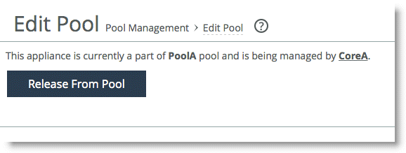
You see the message, “This appliance is currently a part of <pool-name> pool and is being managed by <manager-hostname>.”
2. Click Release me from the Pool.
This action releases the member from the pool, but you continue to see the member in the pool table on the manager.
Figure: Releasing a pool member from the member Management Console
3. Manually delete the released member from the manager pool table.
High availability in pool management
When you use pool management in conjunction with an HA environment, configure both peers as members of the same pool. If you choose one of the peers to be a pool manager, its failover peer should join the pool as a member. Without pool management, Core cannot manage its failover peer storage configuration unless failover is active (the failover peer is down). With pool management, the manager can manage the failover peer storage configuration even while the failover peer is up. The manager failover peer can manage the manager storage configuration only when the manager is down.
The following scenarios show how you can use HA in pool management:
• The manager is down and its failover peer is active.
In this scenario, when the manager is down the failover peer can take over the management of a pool. The manager failover peer can manage storage configuration for the members of the pool using the same configuration as the manager.
• The member is down and its failover peer is active.
When a member of a pool is down and it has a failover peer configured (and the peer is not the manager of the member), the failover peer takes over servicing the LUNs of the member. The failover peer can access the storage configuration of the member when it is down. However, the pool manager cannot access the storage configuration of the failed member. To manage storage configuration of the down member, you need to log in to the Management Console of its failover peer directly.
Note: The pool is dissolved when the manager is no longer available, unless the manager has an HA peer.
Cloud storage gateway support
Cloud storage gateway technology enables organizations to store data in the public cloud and access it using standard storage protocols, like iSCSI, via an appliance on the customer premises. In simple terms, a cloud storage gateway device provides on-premises access for local initiators using iSCSI and connects through to storage hosted in the public cloud using a RESTful API via HTTPS. This approach enables companies to adopt a tiered storage methodology for their data by retaining a “working set” within the data center at the same time as moving older data out to cloud hosting providers.
The individual features and specifications of storage gateway products may vary according to the manufacturer. Such details go beyond the scope of this document.
With Core release 4.3 and later, SteelFusion Core has the ability to support cloud storage gateway technology from Amazon and Microsoft. Depending on the cloud gateway product configured with SteelFusion Core, the cloud storage is either Amazon Web Services S3 (Simple Storage Service) or Microsoft Azure Blob Storage. The Amazon storage gateway product is called AWS Cloud gateway and the Microsoft storage gateway is called StorSimple. These cloud gateway products provide an iSCSI target to SteelFusion Core in exactly the same way as regular “on premises” iSCSI storage arrays would. SteelFusion can now extend the benefits of public cloud storage all the way out to the branch office while continuing to provide the benefits of SteelFusion.
The following SteelFusion Core features are supported with a cloud storage gateway deployment:
• Core and Edge in HA deployment
• Protection against data center failures
• Instant branch provisioning and recovery
• Data security
• Data encrypted at rest on the SteelFusion appliance
• Data encrypted in flight from branch to data center
• Amazon and Microsoft security best practices to encrypt data from data center to cloud
The following SteelFusion Core features are not currently supported:
• Snapshot or data protection of SteelFusion LUNs provided by the cloud gateways
Note: You can always use the respective cloud vendor’s built-in data protection tools to provide the snapshot capability.
Because SteelFusion sees no real difference between on-premises storage arrays and cloud storage gateway, the configuration of SteelFusion Core remains the same with respect to LUN provisioning, access, and use of these LUNs by SteelFusion Edge.
Related information
• SteelFusion Core Management Console User’s Guide
• SteelFusion Edge Management Console User’s Guide
• SteelFusion Core Installation and Configuration Guide
• SteelFusion Command-Line Interface Reference Manual
• Network and Storage Card Installation Guide
• Fibre Channel on SteelFusion Core Virtual Edition Solution Guide
• Riverbed Splash at https://splash.riverbed.com/community/product-lines/steelfusion


