Chapter 4 Packet Collection for SteelCentral : Port Mirroring and SPAN

Port Mirroring and SPAN
This section contains the following topics:
  • Port Mirroring
  • Remote SPAN and Encapsulated Remote SPAN
  • Sample Port Mirror Configurations
  • Cisco Nexus v1000 Virtual Switch SPAN
  • VMware ESXi Distributed vSwitch Port Mirroring Versus Promiscuous Mode
  • Port Mirroring
    Port mirroring is the most popular method for collecting packets. Port mirroring is commonly referred to as switched port analyzer (SPAN). You can use the terms SPAN and port mirroring interchangeably. When you configure port mirroring, depending upon your hardware, you can mirror:
  • select ports or select VLANs from a device to a monitoring port.
  • all ports or all VLANs from the device to a monitoring port.
  • You can also, depending upon your hardware, configure mirroring on ingress, egress, or both, on the interfaces or VLANs you are monitoring.
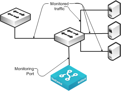
    Figure 4‑1 shows a monitoring configuration in which you detect traffic among all local servers. By monitoring an uplink port or VLAN, in addition to the local ports or VLANs, you can also detect traffic between all external hosts to the local hosts. The NetShark supports up to eight monitoring ports that enable you to duplicate this configuration multiple times using the same NetShark.
    Figure 4‑1. SPAN Connectivity
    Best practices for port mirroring:
  • For most monitoring and troubleshooting, you want to collect both sides of the conversation on a single monitor interface. This means that if you are capturing only a single port, you must mirror both directions—ingress and egress. If you are monitoring all ports or all communicating VLANs, you can capture ingress and egress only. Capturing ingress and egress on all ports or all VLANs is redundant, and the duplicate traffic is deduplicated on the NetShark.
  • When you set up port mirroring, you must follow best practices according to your switch vendor. Because many architectures use nonblocking methods that drop overages if you overrun a port mirror (for example, by sending multiple gigabits per second worth of packets from a single gigabit port), depending on the switch you use, there can be an adverse effect on traffic or switch performance.
  • For large applications across numerous switches, you can use third-party port monitor aggregators for flexible configurations. Vendors that supply port monitor aggregators include, but are not limited to, Anue Systems, NetOptics, Gigamon, cPacket Networks, and VSS Monitoring.
  • Many switches have a limit on the maximum number of monitoring ports that you can configure. This limit is often two monitoring ports. If the limit is a problem in your environment, you can add a TAP to an existing monitoring port (essentially making a copy of the traffic already being monitored by another device), or you can use VLAN access control lists (VACLs) to configure what amounts to an additional SPAN port, provided that your equipment supports VACLs. For more information, see VACL Configuration Examples.
  • Remote SPAN and Encapsulated Remote SPAN
    This section describes the following SPAN variations:
  • RSPAN
  • ERSPAN
  • Riverbed recommends Remote SPAN (RSPAN) and Encapsulated Remote SPAN (ERSPAN) techniques in special circumstances only. With some routers and switches, an adverse impact on performance can occur with configuration of RSPAN or ERSPAN. Read the appropriate documentation and release notes for the hardware and software of your switch or router.
    RSPAN
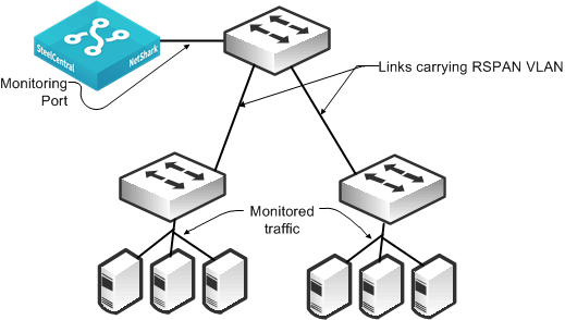
    RSPAN enables an extension of a SPAN over the network to another switch on a Layer-2 nonroutable RSPAN VLAN. You can use RSPAN when you have one or more access switches and you want to configure a SPAN to a single NetShark or NetExpress monitoring port at a distribution switch. To ensure that network traffic is not impeded, dedicate a trunk port to carry the traffic from the access switches to the distribution switch.
    Figure 4‑2 shows a monitoring configuration in which you detect traffic to and from local servers on two different switches. The monitoring port is on an upstream switch. The NetShark and NetExpress have two or more monitoring ports that enable you to duplicate this configuration multiple times using the same NetShark or NetExpress.
    Figure 4‑2. RSPAN Connectivity
    ERSPAN
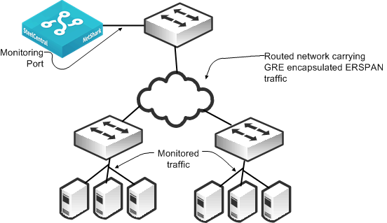
    ERSPAN enables an extension of a SPAN over the network to another switch through a routed GRE-encapsulated tunnel. You can use ERSPAN when a NetShark or NetExpress is monitoring from a distant switch. In this case, you must have adequate bandwidth over the routed path that carries the mirrored traffic so that mirroring does not adversely affect production network traffic.
    Figure 4‑3 shows a monitoring configuration that enables you to detect traffic to and from local servers on two different switches when the monitoring port is on an upstream switch over a routed network. The NetShark and NetExpress have two or more monitoring ports that enable you to duplicate this configuration multiple times using the same NetShark or NetExpress.
    Figure 4‑3. ERSPAN Connectivity
    You must use ERSPAN in a virtualized environment that uses the Cisco Nexus 1000V. The Cisco Nexus 1000V mirrors traffic sent between virtual machines by sending ERSPAN to an external Cisco Catalyst 6500 switch. Take caution when using ERSPAN because it can use a significant amount of bandwidth and resources that send remote traffic.
    Sample Port Mirror Configurations
    This section includes the following SPAN port configuration examples:
  • Cisco Nexus v1000 Virtual Switch SPAN
  • Cisco Catalyst 6500 SPAN
  • Cisco Nexus 5000 SPAN
  • Cisco Nexus 1000V ERSPAN to Cisco Catalyst 6500
  • SPAN port configurations vary depending upon device and software version. For more information, see the documentation that came with your device.
    For details about Cisco switch configuration examples, go to http://www.cisco.com/en/US/products/hw/switches/ps708/products_tech_note09186a008015c612.shtml.
    Cisco Nexus v1000 Virtual Switch SPAN
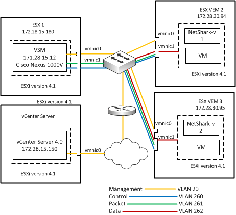
    Figure 4‑4 shows an example Cisco Nexus v1000 virtual switch environment.
    Figure 4‑4. Cisco Nexus v1000 Virtual Switch SPAN
    Consider the following before you begin SPAN configuration:
  • You can configure a maximum of 64 SPAN sessions (Local SPAN plus ERSPAN) on the virtual supervisor module (VSM).
  • A maximum of 32 source VLANs are allowed in a session.
  • A maximum of 128 source interfaces are allowed in a session.
  • You can configure a port in a maximum of four SPAN sessions.
  • You cannot use the destination port in one SPAN session as the destination port for another SPAN session.
  • You cannot configure a port as both a source and destination port.
  • SPAN sessions are created in the shut state by default.
  • When you create a SPAN session that already exists, any additional configuration is added to that session. To make sure the session is cleared of any previous configuration, you can delete the session first.
  • For VLAN SPAN sessions switched on the same VLAN with both receive and transmit configured, two packets (one from receive and one from transmit) are forwarded from the destination port.
    Each local SPAN session must have at least one destination port (also called a monitoring port) that receives a copy of traffic from the source ports or VLANs. A destination port has these characteristics:
  • Can be any physical or virtual Ethernet port or a port channel.
  • Cannot be a source port.
  • Is excluded from the source list and is not monitored if it belongs to a source VLAN of any SPAN session.
  • Receives copies of transmitted and received traffic for all monitored source ports. If a destination port is oversubscribed, it can become congested. This congestion can affect traffic forwarding on one or more of the source ports.
  • Must be on the same host (line card) as the source port.
  • In Local SPAN, the source interface and destination interface are on the same device.
  • To configure a local SPAN session
    configure terminal
    no monitor session session-number
    monitor session session-number
    description description
    source {interface type | vlan | port-profile} {number | range} [rx | tx | both]
    (Optional) Repeat above line to configure additional SPAN sources.
    (Optional) filter vlan {number | range}
    (Optional) Repeat above line to configure all source VLANs to filter.
    destination {interface type | port-profile} {number | range}
    (Optional) Repeat above line to configure all SPAN destination ports.
    no shut
    (Optional) exit
    (Optional) interface ethernet slot/port[-port]
    (Optional) switchport trunk allowed vlan {vlan-range | add vlan-range | except vlan-range | remove vlan-range | all | none}
    (Optional) Repeat above line to configure the allowed VLANs on each destination port.
    (Optional) show interface ethernet slot/port[-port] trunk
    (Optional) copy running-config startup-config
    Cisco Catalyst 6500 SPAN
    The following steps describe how to configure a SPAN for all traffic for VLANs 1 through 100 using a Cisco Catalyst 6500 SPAN. You must only capture ingress on the VLANs to monitor all traffic.
    To configure a SPAN for all traffic for VLANs 1 through 100 using a Cisco Catalyst 6500 SPAN
    1.
    Switch# configure terminal
    Switch(config)# monitor session 1 source vlan 1-100 rx
    2.
    Switch(config)# monitor session 1 destination gigabitethernet 4/3
    The following example shows how to capture all traffic to and from sources on the downstream port 5/1 and send the collected traffic to port 5/3.
    To configure a SPAN for all traffic to and from a downstream switch on port 5/1 using a Cisco Catalyst 6500 SPAN
    1.
    Switch# configure terminal
    Switch(config)# monitor session 1 source gigabitethernet 5/1 both
    2.
    Switch(config)# monitor session 1 destination gigabitethernet 5/3
    Cisco Nexus 5000 SPAN
    The following example shows how to configure a SPAN for all traffic for VLANs 1 to 100. The Cisco Nexus 5000 collects all traffic ingress to the VLANs. The example shows that using a SPAN on ingress works as well as VLANs 1 to 100.
    To configure a SPAN for all traffic for VLANs 1 to 100 using a Cisco Nexus 5000 SPAN
    1.
    Switch# configure terminal
    Switch(config)# monitor session 1
    Switch(config-monitor)# exit
    Switch(config)#
    2.
    Switch(config)# interface ethernet 5/4
    Switch(config-if)# switchport monitor
    Switch(config-if)# exit
    Switch(config-if)# monitor session 1
    Switch(config-monitor)# destination interface ethernet 5/4
    3.
    Switch(config-monitor)# source vlan 1-100
    The following example shows all traffic using SPAN to and from a downstream switch on port 5/2. You want to make sure that you are capturing all traffic to and from sources on the downstream port. Capture traffic in both directions on the port (default if unspecified).
    To configure a SPAN for all traffic to and from a downstream switch on port 5/2 using a Cisco Nexus 5000 SPAN
    1.
    Switch# configure terminal
    Switch(config)# monitor session 1
    Switch(config-monitor)# exit
    Switch(config)#
    2.
    Switch(config)# interface ethernet 5/5
    Switch(config-if)# switchport monitor
    Switch(config-if)# exit
    Switch(config-if)# monitor session 1
    Switch(config-monitor)# destination interface ethernet 5/5
    3.
    Switch(config-monitor)# source interface ethernet 5/2 both
    For additional information about Cisco Nexus 5000 and NetShark, see http://supportkb.riverbed.com/support/index?page=content&id=S24538.
    Cisco Nexus 1000V ERSPAN to Cisco Catalyst 6500
    The following example shows how to configure an ERSPAN for Cisco Nexus 1000V to a Catalyst 6500. You must configure both the Cisco Nexus 1000V and the Catalyst 6500. This example shows data collection from VLANs 1 through 10 on the Cisco Nexus 1000V switch. The example uses a ERSPAN identifier of 100 for the configuration.
    To configure the Cisco Nexus 1000V to collect data on VLANs 1 to 10
    1.
    Switch# configure terminal
    Switch(config)# monitor session 1 type erspan-source
    Switch(config-monitor)# desc cascadeerspansource
    2.
    switch (config-monitor)# source vlan 1-10
    3.
    Switch (config-monitor)# destination ip <6500-ip-address>
    Switch (config-monitor)# erspan-id 100
    Switch (config-monitor)# no shut
    To configure the Cisco Catalyst 6500 to ERSPAN
    1.
    Switch# configure terminal
    Switch(config)# monitor session 1 type erspan-destination
    Switch(config-monitor)# desc cascadeerspansource
    2.
    Switch (config-monitor)# destination interface gix/y/z
    Switch (config-monitor)# source
    Switch (config-monitor)# erspan-id 100
    Switch (config-monitor)# ip address <6500-ip-address>
    Switch (config-monitor)# no shut
    VMware ESXi Distributed vSwitch Port Mirroring Versus Promiscuous Mode
    Port mirroring can mirror all the traffic coming in or going out of particular virtual ports on a virtual distributed switch. Promiscuous mode repeats the traffic it receives to any virtual adapter that has entered promiscuous mode. Promiscuous mode cannot forward traffic to a particular port on the virtual switch. In other words, any virtual machine connected to the port group that is in promiscuous mode can capture the traffic. This behavior makes using promiscuous mode a potential security risk. Riverbed recommends that you consult your account team before you configure promiscuous mode.
    Time Stamping
    NetShark provides software-based time stamping of incoming flows. For some applications, such as certain financial transactions, performing time stamping in software does not provide the level of detail needed. To provide support for the additional granularity needed, the NetShark (but not the NetShark-v) supports external time stamping of incoming packets. NetShark supports time stamps from the following appliances:
  • Gigamon (Header/Trailer/Trailer X12-TS)
  • Anue (requires Advanced Packet Processing module)
  • cPacket
  • VSS (Time stamp Only and Port ID & Time stamp)
  • Arista Packet Broker (Series 7150)
  • Packet Slicing
    Packet slicing is the process of selectively forwarding packets or portions of packets from the packet aggregator to the collector. When a packet is sliced, only a portion of that packet can be forwarded; for example, only the headers are forwarded. When performing packet slicing on a Gigamon 2404 and forwarding the sliced packets to the NetShark, the packet lengths continue to appear correct in both Pilot views and during packet capture (PCAP) export. The payload (or whatever portion of the packet that is sliced off) is not available. There is nothing to configure on the NetShark for proper support of packet slicing from the Gigamon 2404.