Validating the path selection design
Use these pages to validate your design:
• Choose Networking > Network Services: Path Selection to view the Uplink Status table. Click the uplink name for details such as number of bytes sent, peer availability, and uplink status.
• Reports > Networking: Current Connections shows details per connection.
• Reports > Networking: Interface Counters shows that the traffic in a multi-interface deployment is exiting the correct interface.
To troubleshoot, we recommend taking TCP dump traces on all WAN and LAN interfaces.
Using an interface and next hop IP address to select an uplink
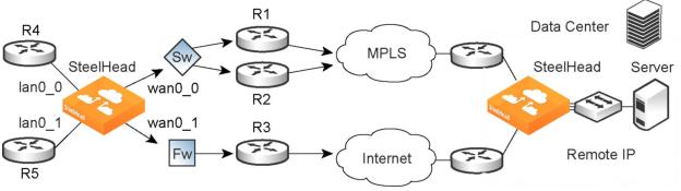
In this configuration, you have multiple uplinks from the appliance to the remote data center. The appliance selects which uplink to use. For each application, you define the primary uplink as a combination of the outgoing interface (wan0_0 or wan0_1) and the next hop IP address. The system must send the probe packets over the exact uplink that the data packets take.
Path selection by relay interface and next hop IP address
You can define this type of configuration in one of these ways:
• Define the uplinks using only the relay interface—In this configuration, you define a primary uplink by specifying the wan0_0 interface and the secondary uplink as the wan0_1 interface. Suppose that the appliance selects the primary uplink for the application. In this case, it does not matter whether it sends the packet to path 1 or path 2. In both cases, the appliance selects the MPLS uplink.
While probing for the remote IP address from wan0_0, the probe packets use either R1 or R2. The appliance cannot monitor both uplinks because it does not know about them. Because it monitors only one uplink, it ensures that all data packets are also sent over that uplink. Assuming that the probe packets are being sent to the remote IP through R1, it cannot use uplink 2 to send data packets toward the server, because this uplink might be down. The appliance does not route data packets, but simply uses the next hop learnt by probing.
In the case of the secondary uplink, all packets are sent through uplink 2 so there is no confusion.
• Define the uplinks using an interface and the next-hop IP address—In this configuration, you specify the next hop as well as the relay interface to use for a given uplink. This is the simplest case, because the appliance does not need to learn anything during probing. The appliance does not need to route data packets, because they use the next hop specified in the configuration. The appliance sends the packets out of the configured relay.
For more use cases, see the SteelHead Deployment Guide.