Figure: In-Path Interfaces Page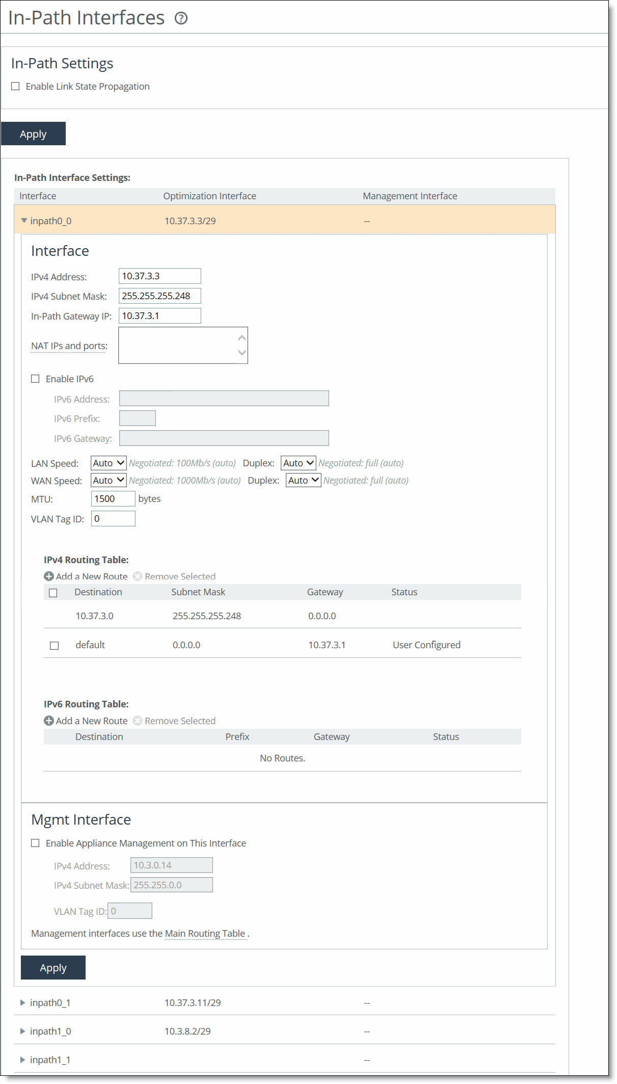
Control | Description |
Enable Link State Propagation | Enables this control to shorten the recovery time of a link failure in physical in-path deployments. Link state propagation (LSP) communicates link status between the devices connected to the SteelHead. When you enable this LSP, RiOS monitors the link state of each SteelHead LAN-WAN pair. If either physical port loses link status, the corresponding interface disconnects, blocking the link. This control allows a link failure to quickly propagate through a chain of devices. If the link recovers, the SteelHead restores the corresponding interface automatically. LSP is enabled by default. Note: You can’t reach a MIP interface when LSP is also enabled and the corresponding in-path interface fails. These SteelHead (virtual edition) appliance configurations don’t support LSP: • SteelHead-v models running ESX/ESXi 4.0 or 4.1 • SteelHead-v models running Microsoft Hyper-V • SteelHead-v models running RiOS 8.0.2 and earlier |
Control | Description |
IPv4 Address | Specify an IP address. This IP address is the in-path main interface. |
IPv4 Subnet Mask | Specify the subnet mask. |
In-Path Gateway IP | Specify the IP address for the in-path gateway. If you have a router (or a Layer-3 switch) on the LAN side of your network, specify this device as the in-path gateway. Note: If there’s a routed network on the LAN-side of the in-path appliance, the router that is the default gateway for the appliance must not have the ACL configured to drop packets from the remote hosts as its source. The in-path appliance uses IP masquerading to appear as the remote server. |
NAT IPs and Ports | In the case of UDP encapsulation with NAT, different SteelHeads could use the same public-facing destination addresses. To uniquely identify such SteelHeads, specify a NAT IPv4 address paired with a specific port opened on the NAT. Specify multiple NAT IPs and ports on separate lines. |
Enable IPv6 | Select this check box to assign an IPv6 address. IPv6 addresses are disabled by default. You can only assign one IPv6 address per in-path interface. Note: The primary and in-path interfaces can share the same subnet. The primary and auxiliary interfaces can’t share the same network subnet. |
IPv6 Address | Specify a global or site-local IPv6 address. This IP address is the in-path main interface. You can’t use a DHCP server to assign an IPv6 address automatically. |
IPv6 Prefix | Specify the prefix. The prefix length is 0 to 128 bits, separated from the address by a forward slash (/). In the following example, 60 is the prefix: 2001:38dc:52::e9a4:c5:6282/60 |
IPv6 Gateway | Specify the IPv6 address for the in-path gateway. You can use a link local address. If you have a router (or a Layer-3 switch) on the LAN side of your network, specify this device as the in-path gateway. Note: If there’s a routed network on the LAN-side of the in-path appliance, the router that is the default gateway for the appliance must not have the ACL configured to drop packets from the remote hosts as its source. The in-path appliance uses IP masquerading to appear as the remote server. |
LAN Speed and Duplex WAN Speed and Duplex | Speed - Select Auto, 1000, 100, or 10 from the drop-down list. The default value is Auto. Duplex - Select Auto, Full, or Half from the drop-down list. The default value is Auto. If your network routers or switches don’t automatically negotiate the speed and duplex, be sure to set them on the device manually. The speed and duplex must match (LAN and WAN) in an in-path configuration. To avoid a speed and duplex mismatch, configure your LAN external pair to match the WAN external pair. Note: Speed and duplex mismatches can easily occur in a network. For example, if one end of the link is set at half or full-duplex and the other end of the link is configured to autonegotiate (auto), the link defaults to half-duplex, regardless of the duplex setting on the nonautonegotiated end. This duplex mismatch passes traffic, but it causes interface errors and results in degraded optimization. These guidelines can help you avoid speed and duplex mismatches when configuring the SteelHead: • Routers are often configured with fixed speed and duplex settings. Check your router configuration and set it to match the SteelHead WAN and LAN settings. Make sure that your switch has the correct setting. • After you finish configuring the SteelHead, check for speed and duplex error messages (cyclic redundancy check (CRC) or frame errors) in the System Log page of the Management Console. • If there’s a serious problem with the SteelHead and it goes into bypass mode (that is, it automatically continues to pass traffic through your network), a speed and duplex mismatch might occur when you reboot the SteelHead. To avoid a speed and duplex mismatch, configure your LAN external pair to match the WAN external pair. |
MTU | Specify the MTU value. The MTU is the largest physical packet size, measured in bytes, that a network can send. Applies to optimized traffic only. The default value is 1500. |
VLAN Tag ID | Specify the VLAN tag that the appliance uses to communicate with other SteelHeads in your network. The VLAN Tag ID might be the same value or a different value than the VLAN tag used on the client. A zero (0) value specifies nontagged (or native VLAN) and is the correct setting if there are no VLANs present. As an example, if the in-path interface is 192.168.1.1 in VLAN 200, you would specify tag 200. When the SteelHead communicates with a client or a server, it uses the same VLAN tag as the client or the server. If the SteelHead can’t determine which VLAN the client or server is in, it doesn’t use the VLAN tag (assuming that there’s no router between the SteelHead and the client or server). You must also define in-path rules to apply to your VLANs. |
Control | Description |
Add a New Route | Displays the controls to add a route. |
Destination IP Address | Specify the destination IP address. |
Gateway IP Address | Specify the IP address for the gateway. The gateway must be in the same network as the in-path interface. |
Add | Adds the route to the table list. |
Remove Selected | Select the check box next to the name and click Remove Selected. |
Control | Description |