About sites and networks settings
Settings for the network connectivity view are under Networking > Topology: Sites & Networks.
Sites & Networks page
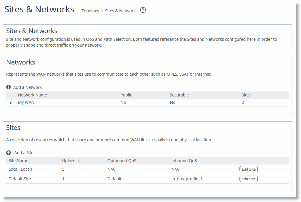
Networks represent the WAN networks that connect sites. Adding a network is simple. Just enter a name and specify whether the network is public. You can’t delete the default network.
A site is a group of subnets that share one or more common uplinks to the WANs that connect sites to each other. By default, each appliance includes a predefined local site and remote site, which you can edit but cannot delete. In site definitions, every subnet must be globally unique, although they can overlap.
When you define sites in the SteelCentral Controller for SteelHead, you don’t have to specify the IP addresses of the managed appliances at each given site, because the SCC dynamically adds them to the site configuration.
Site name
Enter a descriptive name for the site.
Network information
Optionally, enter a subnet IP prefix for a set of IP addresses on the site’s LAN-side. Separating multiple subnets with commas. Appliances determine the destination site using a longest-prefix match on the site subnets. For example, if you define site 1 with 10.0.0.0/8 and site 2 with 10.1.0.0/16, then traffic to 10.1.1.1 matches site 2, not site 1. Consequently, the default site defined as 0.0.0.0 only matches traffic that doesn’t match any other site subnets.
You can also specify the IP addresses of peer appliances. This is useful for path selection monitoring and GRE tunneling. Separate multiple peers with commas. The appliance polls the listed peers, in order, to monitor path availability, or considers them the destinations at the end of GRE tunnels. We strongly recommend that you use the remote SteelHead in-path IP address as a peer address when possible.
QoS profiles
Optionally, select inbound and outbound QoS profiles to fine-tune traffic behavior for each site.
Uplinks
An uplink represents the last network segment connecting a site to WAN networks. You can define multiple uplinks for a site. Appliances monitor uplink status and, based on this, select the appropriate uplink for each packet. If one uplink fails, the appliace directs traffic through another available uplink. When the original uplink comes back up, the appliance redirects the traffic back to it.
Common uplink settings include name, network, and up and down bandwidth. Uplink settings for the local site have more options than those for other sites. The additional settings allow you to:
• differentiate between in-path and primary interfaces.
• specify a gateway IP address.
• specify a differentiated services code point (DSCP) marking for upstream router packet steering.
• enable generic route encapsulation (GRE) tunneling if the appliance you are configuring is behind a firewall.
• enable uplink status probing, setting a timeout for probe responses and threshold number of packets lost.
You can configure up to 1024 direct uplinks.
We recommend using the same name for an uplink in all sites connecting to the same network. If you later use an SCC to manage the appliance, it will group uplinks by their names. A topology doesn’t allow duplicate uplinks.
For uplink bandwidth settings, the appliance uses the specified bandwidth to precompute the end-to-end bandwidth for QoS. The uplink rate is the bottleneck WAN bandwidth, not the interface speed out of the WAN interface into the router or switch. Different WAN interfaces can have different WAN bandwidths; you must enter the bandwidth link rate correctly for QoS to function properly.