3080 appliance front panel with LEDs and buttons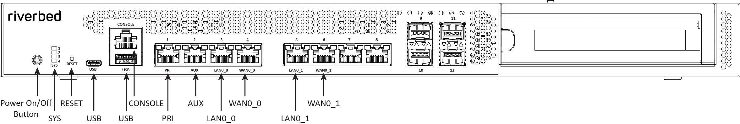
LED or button | Description |
Power On/Off Button and Integrated LED | On = Blue (System is turned on.) Sleep State = Yellow (System is in S5 sleep state.) Off = No light (Power is off.) |
System LEDs | The combination of LED 1 and LED 2 defines the system state: LED 1 = Yellow, LED 2 = Yellow, System State = Critical LED 1 = Yellow, LED 2 = Green, System State =Degraded LED 1 = Green, LED 2 = Green, System State = Healthy LED 3 - Not used; default is off LED 4 - Not used; default is off |
Reset Button | Press to restore factory defaults. |
Console port | RJ45 port |
USB Ports v3.0 | 1 - USB Type A port 1 - USB Type C port |
Port 1 PRI = Primary port | Left LED Link = Green Activity = Blinks green Right LED 10 Mbps data rate = No light (with link on left LED) 100 Mbps data rate = Green 1000 Mbps data rate = Yellow |
Port 2 AUX = Auxiliary port | Left LED Link = Green Activity = Blinks green Right LED 10 Mbps data rate = No light (with link on left LED) 100 Mbps data rate = Green 1000 Mbps data rate = Yellow |
Ports 3-6 LAN/WAN ports | Left LED Link = Green Activity = Blinks green Bypass/Disconnect = Yellow Right LED 10 Mbps data rate = No light (with link on left LED) 100 Mbps data rate = Green 1000 Mbps/1 Gbps = Yellow |
Ports 7-8 (on-board) | Not used. |
LED/button | Description |
HDDs | Activity LED (upper light) Activity = Blinks green (drive present, with activity. Status LED (lower light) Failed Disk = Solid amber |
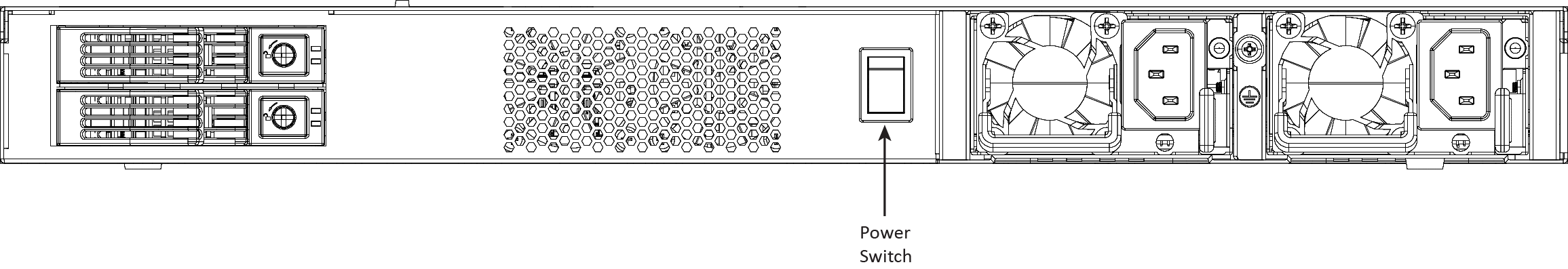
Power Supply LEDs | Power on and healthy = Green Standby = 1 Hz blinks green Power Off = Off Unplugged or power lost but second power supply has power = Amber (for about 5 seconds) then turns Off Power on with warning = 1 Hz blinks amber (Indicates high temperature, high power, high current, or slow fan.) |
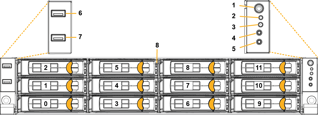
Reference | LED/button | Description |
1 | Power On/Off Button and Integrated LED | On = Green (System is turned on.) Sleep State = Green (System is in S1 or S3 sleep state.) Off = No light (Power is off.) |
2 | IPMI Warning LED | The IPMI Warning LED shows the current health of the server system. Normal = Green (No failures) Degraded/Warning = Amber (Indicates fan failure, high temperature, over voltage, or power supply failure.) Critical = Blinks amber and Green (Indicates a problem that needs attention, such as optimization service down, no license, or in_path is not enabled for optimization service.) |
3 | ID LED | On = Blue (System identified remotely on the server.) Off = Off (System not identified.) |
4 | Reset Button | Press to reboot the appliance. |
5 | System ID Button | Press the system ID button when the system AC (alternating current) is on. The system ID LED indicates the system is identified with a blue light. Users from a remote site can activate the ID LED by inputting commands in IPMI. For details, contact Support. |
6, 7 | USB Ports v2.0 | |
8 | HDD/SSD LEDs | Activity LED (lower light) Link = Green (Drive present, with no activity.) Activity = Blinks green (Drive present, with activity.) Status LED (upper light) Failed Disk = Solid red |
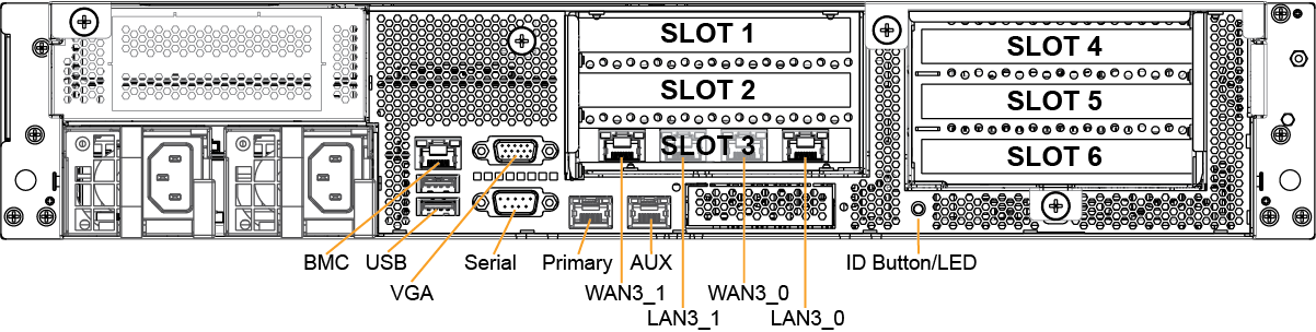
LED/button | Description |
ID LED/Button | On = Blue (System identified remotely on the server.) Off = Off (System not identified.) Press the system ID button when the system AC (Alternating Current) is on. The system ID LED indicates the system is identified with a blue light. Users from a remote site can activate the ID LED by inputting commands in IPMI. For details, contact Support at https://support.riverbed.com. |
Primary and AUX Port LEDs | Left LED Link = Green Activity = Blinks green No Link = Off Right LED 10 Mbps = Off 100 Mbps = Green 1000 Mbps = Amber |
Four-Port 1 GbE Copper Bypass Card LEDs (preinstalled) | Link/Activity LED Link = Green Activity = Blinks green Speed/Bypass/Disconnect LED 1000 Mbps = Yellow 100 Mbps = Green 10 Mbps = Off Bypass = Blinks green Disconnect = Blinks yellow |
Power Supply LEDs | Power on and healthy = Green Standby = Blinks green Power Off = Off Unplugged or power lost but second power supply has power = Amber (for about 5 seconds) then turns Off Power on with warning = Blinks amber (indicates high temperature, high power, high current, or slow fan) |