Defining tunneled uplinks
RiOS 8.6 and later include a tunnel mode to provide IPv4 generic routing encapsulation (GRE) for direct uplinks. Direct uplinks using GRE become direct tunneled uplinks. You must create direct tunneled uplinks to steer traffic over any uplink that traverses a stateful firewall between the server-side SteelHead and the client-side SteelHead.
Without GRE, traffic attempting to switch midstream to an uplink that traverses a stateful firewall might be blocked. The firewall needs to track the TCP connection state and sequence numbers for security reasons. Because the firewall has not logged the initial connection handshake, and has partial or no packet sequence numbers, it blocks the attempt to switch to the secondary uplink and might drop these packets. To traverse the firewall, path selection can encapsulate that traffic into a GRE tunnel. The most common examples of midstream uplink switching occur when:
• a high-priority uplink fails over to a secondary uplink that traverses a firewall.
• a previously unavailable uplink recovers and resumes sending traffic to a firewalled uplink.
• path selection is using the Application File Engine (AFE) to identify the traffic and doesn’t yet recognize the first packets of a connection before traversing a default uplink.
The GRE tunnel starts with a SteelHead and ends at the remote SteelHead. Both SteelHeads must be running RiOS 8.6.x or later. The tunnel configuration is local. The remote IP address must be a remote SteelHead in-path interface and the remote SteelHead must have path selection enabled. ICMP responses from the remote SteelHead use the same tunnel from which the ping is received. The remote SteelHead must also have GRE tunnel mode enabled if the user wants return traffic to go through a GRE as well.
New Uplink dialog box
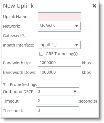
1. Specify the uplink name (for example, MPLS1). We recommend using the same name for an uplink in all sites connecting to the same network. If you later use an SCC to maintain the SteelHeads, it will group uplinks by their names to simplify the configuration of new sites. Each uplink must have a unique interface, gateway, and probe DSCP setting. A topology doesn’t allow duplicate uplinks.
2. Select a network from the drop-down list. Optionally, specify a gateway IP address for path selection. Specify an in-path interface.
3. Optionally, click GRE Tunneling to provide IPv4 generic routing encapsulation (GRE) for direct uplinks used in path selection. Direct uplinks using GRE become direct tunneled uplinks. You must create direct tunneled uplinks to steer traffic over any uplink that traverses a stateful firewall between the server-side SteelHead and the client-side SteelHead. Without GRE, traffic attempting to switch midstream to an uplink that traverses a stateful firewall might be blocked. The firewall needs to track the TCP connection state and sequence numbers for security reasons. Because the firewall has not logged the initial connection handshake, and has partial or no packet sequence numbers, it blocks the attempt to switch to the secondary uplink and might drop these packets. To traverse the firewall, path selection can encapsulate that traffic into a GRE tunnel.
4. Specify the up and down bandwidth in kilobits per second. RiOS uses the bandwidth to precompute the end-to-end bandwidth for QoS. The SteelHead automatically sets the bandwidth for the default site to this value. The uplink rate is the bottleneck WAN bandwidth, not the interface speed out of the WAN interface into the router or switch. As an example, if your SteelHead connects to a router with a 100-Mbps link, don’t specify this value—specify the actual WAN bandwidth (for example, T1, T3). Different WAN interfaces can have different WAN bandwidths; you must enter the bandwidth link rate correctly for QoS to function properly.
5. Optionally, click the right-arrow and specify the probe settings for path selection monitoring.
Outbound DSCP
Select the DSCP marking for the ping packet. You must select this option if the service providers are applying QoS metrics based on DSCP marking and each provider is using a different type of metric. Path selection-based DSCP marking can also be used in conjunction with policy-based routing (PBR) on an upstream router to support path selection in cases where the SteelHead is more than a single Layer-3 hop away from the edge router.
The default marking is preserve. Preserve specifies that the DSCP level or IP ToS value found on pass-through and optimized traffic is unchanged when it passes through the SteelHead.
Timeout
Specify how much time, in seconds, elapses before the system considers the uplink to be unavailable. The default value is 2 seconds.
RiOS uses ICMP pings to probe the uplinks. If the ping responses don’t make it back within this timeout setting and the system loses the number of packets defined by the threshold value, it considers the uplink to be down and triggers the path selection Path Down alarm.
Threshold
Specify how many timed-out probes to count before the system considers the uplink to be unavailable and triggers the Path Down alarm. The default is three failed successive packets.
This value also determines how many probes the system must receive to consider the uplink to be available.
RiOS uses ICMP pings to monitor uplink availability. If the ping responses don’t make it back within the probe timeout and the system loses the number of packets defined by this threshold, it considers the uplink to be down and triggers the path 9.5 selection Path Down alarm.
After saving your configuration changes, the sites appear in the table. The default site matches all of the traffic that doesn’t match another site.
About GRE tunnel optimization
Starting with RiOS 9.7, Generic Routing Encapsulation (GRE) between two SteelHead appliances can be inspected and optimized. Enable the GRE tunnel optimization features with the in-path peering-gre command.
Supported topologies for GRE tunnel optimization
GRE optimization supports hub-and-spoke and spoke-to-spoke topologies. A maximum of 100 tunnels is supported on a hub-and-spoke topology or a spoke-to-spoke topology.
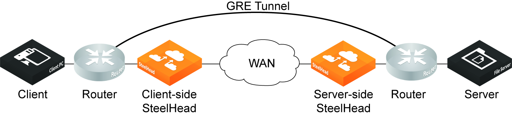
The GRE tunnel must be started and terminated between two routers. In addition, the default route for the client-side SteelHead and server-side SteelHeads should be directed to the WAN. Multiple SteelHead appliances can be used in a point-to-point GRE tunnel, as long as all of the SteelHeads are inside the tunnel.
This figure shows a sample supported topology for GRE optimization.
Simple topology example for GRE optimization
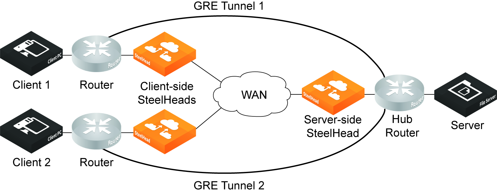
This figure shows a spoke-to-spoke topology with two GRE tunnels. Two client-side SteelHeads and a single server-side SteelHead terminate the optimized connections.
Simple spoke-to-spoke topology for GRE optimization
Supported appliances
The following SteelHead appliances support GRE tunnel optimization:
• CX 3070, 5070, 7070, 3080, 5080, 7080 SteelHead appliances
• SteelHead-v appliances on both KVM and ESXi platforms
Supported features
The following features are supported with GRE tunnel optimization:
• TCP optimization and pass-through
• FTP optimization
• HTTP/HTTPS optimization
• SMBv2 optimization
• NFS optimization
• Video over HTTP/HTTPS optimization
• MAPI optimization
• MX-TCP QoS support
• Simplified routing
• VLAN support
• Full transparency and correct addressing WAN visibility modes
Unsupported features
The following traffic is not optimized with GRE tunnel optimization:
• Out-of-band (OOB) traffic is not optimized. If OOB connections are received from a GRE tunnel, they will be relayed instead of optimized.
• Checksum, key, and sequence numbers are not optimized.
The following features are not supported:
• Asymmetric routing
• QoS classification (except MX-TCP)
• Single-ended interception
• Web Cache Communication Protocol (WCCP)
• Policy-based routing (PBR)
• UDP
• IPv6
• Port transparency WAN visibility mode (full transparency and correct addressing are supported)
• Path selection
• Double interception
• Asymmetric routing
• Interceptor support