Base Interfaces page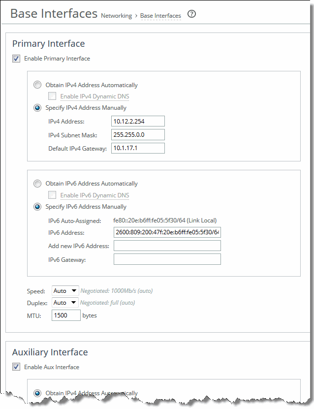
Control | Description |
Enable Primary Interface | Select the check box to enable the primary interface. |
Obtain IPv4 Address Automatically | Select this option to automatically obtain the IPv4 address from a DHCP server. A DHCP server must be available so that the system can request the IP address from it. Optionally, select Enable IPv4 Dynamic DNS to include the appliance hostname with the DHCP request. The primary and in-path interfaces can share the same subnet. The primary and auxiliary interfaces cannot share the same network subnet. |
Specify IPv4 Address Manually | Select this option if you do not use a DHCP server to set the IP address. Specify these settings: • IPv4 Address—Specify an IP address. • IPv4 Subnet Mask—Specify a subnet mask. • Default IPv4 Gateway—Specify the primary gateway IP address. The primary gateway must be in the same network as the primary interface. You must set the primary gateway for in-path configurations. |
Obtain IPv6 Address Automatically | Select this option to automatically obtain the IPv6 address from a DHCP server. A DHCP server must be available so that the system can request the IP address from it. Optionally, select Enable IPv6 Dynamic DNS to include the appliance hostname with the DHCP request. The primary and in-path interfaces can share the same subnet. The primary and auxiliary interfaces cannot share the same network subnet. |
Specify IPv6 Address Manually | Select this option and specify the settings below to set an IPv6 address. You can set multiple IPv6 addresses for the primary interface. • IPv6 Auto-Assigned—Displays the link-local address that is automatically generated when IPv6 is enabled on the base interfaces. • IPv6 Address—Specify an IPv6 address and an IPv6 prefix. – For the IPv6 address, use this format: eight 16‑bit hexadecimal strings separated by colons, 128-bits. For example: 2001:38dc:0052:0000:0000:e9a4:00c5:6282 You do not need to include leading zeros. For example: 2001:38dc:52:0:0:e9a4:c5:6282 You can replace consecutive zero strings with double colons (::). For example: 2001:38dc:52::e9a4:c5:6282 – For the IPv6 prefix, use this format: a number from 0 to 128, separated from the IPv6 address by a forward slash (/). In this example, 60 is the prefix: 2001:38dc:52::e9a4:c5:6282/60 Use the IPv6 Address field to modify or delete the IPv6 address. Enter the new information (or delete the information displayed), and click Apply. The Add New IPv6 Address field lets you add more than one IPv6 address and prefix to your interface. However, if you later select Obtain IPv6 Automatically and click Apply, all of the new IPv6 addresses you added manually will be deleted. • Add New IPv6 Address—Specify new IPv6 addresses to be added to the interface. Use the same formats as specified for the IPv6 Address field above. • IPv6 Gateway—Specify the default gateway IP address. The gateway must be in the same network as the primary interface. You can set an IPv6 address dynamically using a DHCP server. |
Speed | Select a speed from the drop-down list. The default value is Auto. |
Duplex | Select a choice from the drop-down list. The default value is Auto. If your network routers or switches do not automatically negotiate the speed and duplex, be sure to set them manually. The speed and duplex must match (LAN and WAN) in an in-path configuration. If they do not match, you might have a large number of errors on the interface when it is in bypass mode, because the switch and the router are not set with the same duplex settings. |
MTU | Specify the MTU value. The MTU is the largest physical packet size, measured in bytes, that a network can send. The default value is 1500. |
Control | Description |
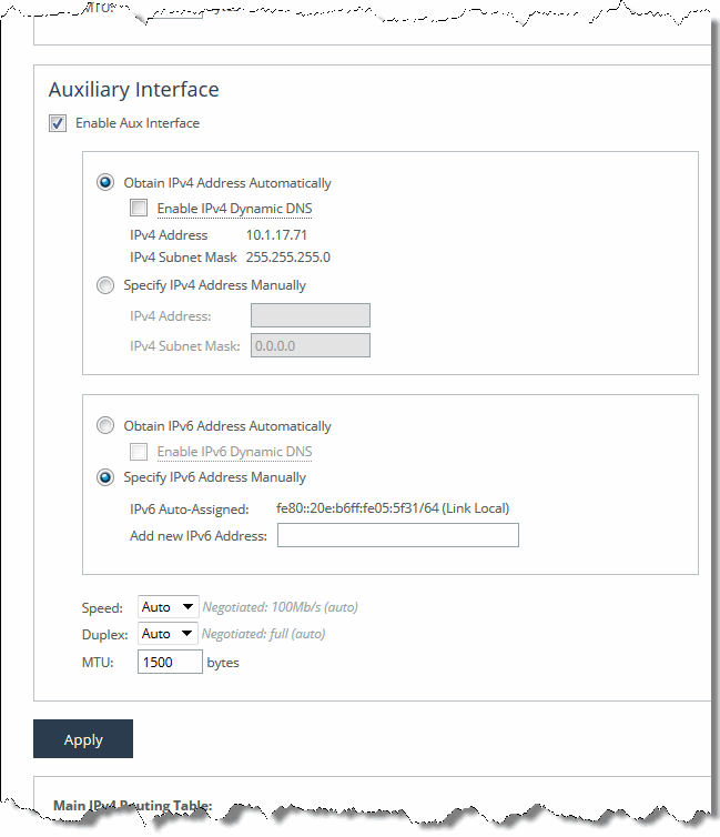
Enable Aux Interface | Enables an auxiliary interface. |
Obtain IPv4 Address Automatically | Select this option to set the appliance to automatically obtain the IP address. Optionally, select Enable IPv4 Dynamic DNS to include the appliance hostname with the DHCP request. The system displays the current IPv4 address and IPv4 subnet mask. The primary and auxiliary interfaces cannot share the same network subnet. The auxiliary and in-path interfaces cannot share the same subnet. You cannot use the auxiliary port for out-of-path SteelHead Interceptors. |
Specify IPv4 Address Manually | Specify these settings: • IPv4 Address—Specify an IP address. • IPv4 Subnet Mask—Specify a subnet mask. Select this option if you do not use a DHCP server to set the IP address. |
Obtain IPv6 Address Automatically | Select this option to automatically obtain the IPv6 address from a DHCP server. A DHCP server must be available so that the system can request the IP address from it. Optionally, select Enable IPv6 Dynamic DNS to include the appliance hostname with the DHCP request. The primary and in-path interfaces can share the same subnet. The primary and auxiliary interfaces cannot share the same network subnet. |
Specify IPv6 Address Manually | Specify these settings: • IPv6 Auto-Assigned—Displays the automatic IP address automatically assigned. • Add New IPv6 Address—Specify new IPv6 addresses to be added to the interface. – For the IPv6 address, use this format: eight 16‑bit hexadecimal strings separated by colons, 128-bits. For example: 2001:38dc:0052:0000:0000:e9a4:00c5:6282 You do not need to include leading zeros. For example: 2001:38dc:52:0:0:e9a4:c5:6282 You can replace consecutive zero strings with double colons (::). For example: 2001:38dc:52::e9a4:c5:6282 – For the IPv6 prefix, use this format: a number from 0 to 128, separated from the IPv6 address by a forward slash (/). In this example, 60 is the prefix: 2001:38dc:52::e9a4:c5:6282/60 The Add New IPv6 Address field lets you add more than one IPv6 address and prefix to your interface. However, if you later select Obtain IPv6 Automatically and click Apply, all of the new IPv6 addresses you added manually will be deleted. |
Speed | Select the speed from the drop-down list. The default value is Auto. |
Duplex | Select a choice from the drop-down list. The default value is Auto. If your network routers or switches do not automatically negotiate the speed and duplex, be sure to set them on the device manually. The speed and duplex must match (LAN and WAN) in an in-path configuration. To avoid a speed and duplex mismatch, configure your LAN external pair to match the WAN external pair. |
MTU | Specify the MTU value. The MTU is the largest physical packet size, measured in bytes, that a network can send. The default value is 1500. |
Control | Description |
Add a New Route | Displays the controls to add a new route. |
Destination IPv4 Address | Specify the destination IPv4 address for the out-of-path appliance or network management device. |
IPv4 Subnet Mask | Specify the IPv4 subnet mask. |
Gateway IPv4 Address | Specify the IPv4 address for the gateway. |
Interface | Select the interface for routing from the drop-down list. |
Add | Adds the route to the table list. |
Remove Selected | Select the check box next to the name and click Remove Selected. |
Control | Description |
Add a New Route | Displays the controls to add a new route. |
Destination IPv6 Address | Specify the destination IPv6 address for the out-of-path appliance or network management device. |
IPv6 Prefix | Specify the prefix. |
Gateway IPv6 Address | Specify the IPv6 address for the gateway. |
Interface | Select the interface for routing from the drop-down list. |
Add | Adds the route to the table list. |
Remove Selected | Select the check box next to the name and click Remove Selected. |