Replacing Fans
The following sections describe how to replace fans in the SteelHead xx50 appliances. These appliances are equipped with hot-swappable fans.
Determining Fan Status
This section describes how to determine the status of individual fans in the appliance.
To determine fan status
1. Connect to the CLI.
For details, see the Riverbed Command-Line Interface Reference Manual.
2. At the system prompt, enter show stats fan:
amnesiac> show stats fan
FanId RPM Min RPM Status
0 4963 1080 ok
1 4963 1080 ok
2 4821 1080 ok
3 4963 1080 ok
4 4963 1080 ok
5 4821 1080 ok
The output and number of fans will vary depending on your appliance.
Replacing Fans in the Interceptor 9350 Appliances
This section describes how to replace fans in the Interceptor 9350. These appliances are equipped with four hot-swappable fans at the front of the chassis and two hot-swappable fans at the back of the chassis.
Note: You must use approved fans. To order fans, contact your sales representative.
Fan Locations
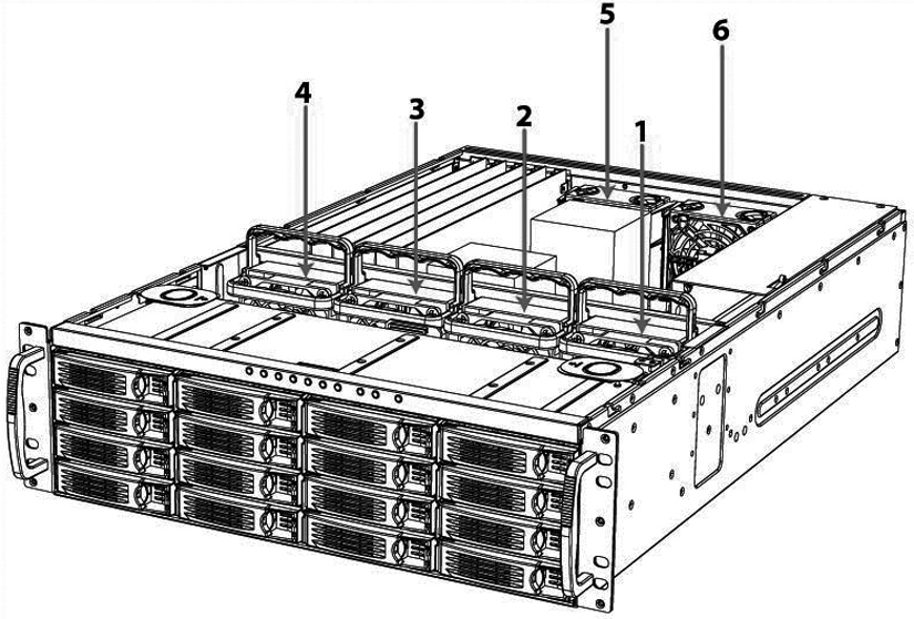
This section provides an overview of fan locations and fan labels in Interceptor 9350. These appliances are equipped with four fans at the front of the chassis and two fans at the back.
Fan ID | Physical Label |
1 | Fan 1 |
2 | Fan 2 |
3 | Fan 3 |
4 | Fan 4 |
5 | Fan 5 |
6 | Fan 6 |
Figure: Interceptor 9350 Fan Layout with Fan ID Numbers
To replace the front fans
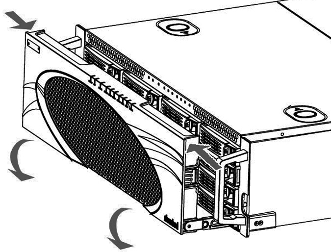
1. To open the bezel, press the buttons on each side of the bezel and pull toward you.
The bezel remains attached to the appliance on hinges.
Figure: Opening the Appliance Bezel
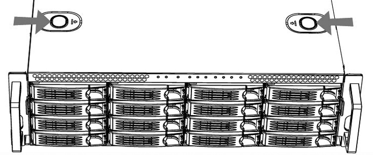
2. To remove the front appliance cover, press in the two buttons on top of the cover and slide the cover forward, and then lift up and away from the chassis.
Figure: Removing the Front Appliance Cover
3. Identify the faulty fan.
4. Pull the fan release lever upwards and pull the fan up from the chassis.
Figure: Releasing the Fan
5. Plug the replacement fan into the chassis.
6. Replace the chassis front cover.
To replace the front cover, insert the rear edge of the front cover below the front edge of the rear cover.
Note: The RiOS IPMI alarm triggers when the chassis cover opens on these appliances while the system is running. To clear this alarm, run the clear hardware error-log command in the CLI. For details, see the Riverbed Command-Line Interface Reference Manual.
To replace the rear fans
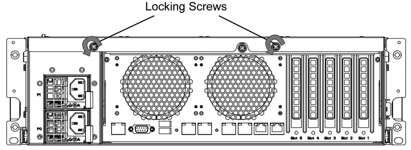
1. To remove the rear appliance cover, loosen the two locking screws on the back of the appliance.
Figure: Loosening the Locking Screws
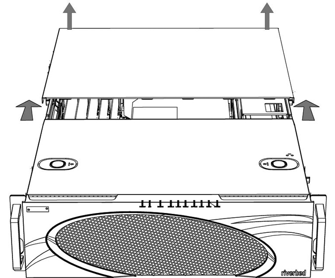
2. Slide the rear cover backward several inches, and then lift up and away from the chassis.
Figure: Removing the Rear Cover from the Chassis
3. Identify the faulty fan.
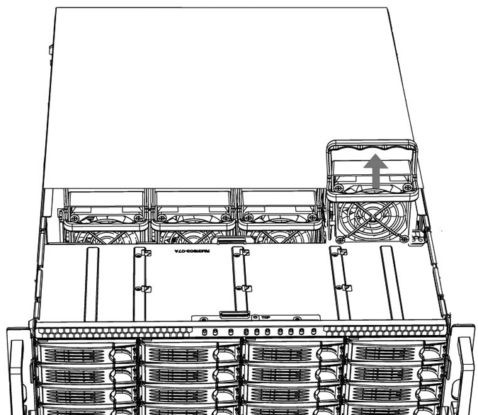
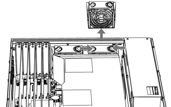
4. Press the buttons on the top of the fan inwards and pull the fan up from the chassis.
Figure: Releasing the Fan
5. Plug the replacement fan into the chassis.
6. Replace the chassis cover.
Note: The RiOS IPMI alarm is triggered when the chassis cover is opened on these appliances while the system is running. To clear this alarm, enter the clear hardware error-log command in the CLI. For details, see the Riverbed Command-Line Interface Reference Manual.
Replacing the Motherboard in SteelHead 7050 Appliances
For the SteelHead 7050 appliance, you can replace the motherboard. Work with Riverbed Support to complete these steps.
Note: A video showing these instructions is on the Riverbed Support Site:
https://support.riverbed.com/kb/multimedia.htm.
To replace a motherboard in a 7050 appliance
1. Power down the system.
2. Disconnect the power cord.
3. Remove the cover.
4. Loosen the motherboard locking screw at the back of the chassis and pull the motherboard handle downward.
The motherboard will slide out 1 to 2 inches from the chassis.
5. Continue sliding the motherboard completely from the chassis.
Caution: 
Be sure to use both hands as the motherboard is heavy.
6. Following the same procedure, remove the replacement motherboard from the chassis.
Each motherboard ships within a chassis.
7. Place the two motherboards side by side.
This helps transfer the appropriate components.
8. Using a Phillips screwdriver, remove the flash drive from the replacement motherboard.
9. Discard this flash drive.
10. Remove the flash drive from the failed motherboard and add it to the replacement motherboard.
Align the pins and secure the flash drive with the Phillips screw.
11. Move the network cards from the failed motherboard to the replacement motherboard.
Move the cards one at a time and keep the cards in the same positions. You will need to remove the slot covers for each network card to transfer. See the Network Interface Card Installation Guide for details.
12. Move the SDR acceleration card to the new motherboard.
Use the same procedure as you did with the network cards.
13. Insert the new motherboard into the chassis. Carefully align it inside the chassis, and slide it into place.
14. For the last inch, move the handle into the upright position and secure it with the locking screw.
15. Replace the back cover and secure it with the fasteners.
16. Connect the power and start the appliance.
17. From the command line, enter configuration mode and enter the show licenses command.
The output indicates the existing licenses are invalid.
18. Write down the MAC addresses of primary, AUX, lan0_0, wan0_0, lan0_1, and wan0_1.
19. Enter the CLI command support motherboard update.
Note: After you enter the command, do not press Ctrl+C before the command completes. You will destroy the BIOS. Restart the appliance when prompted using the reload command.
The commands take a while to complete as they copy the BIOS and reconfigure the MAC addresses.
The support motherboard update command is a hidden command.
20. When prompted, reboot the appliance using the reload command.
21. Once the appliance reboots, enter the show licenses command and ensure that the licenses are valid.
22. Verify the MAC addresses of the primary and AUX interfaces.
The primary and AUX interfaces should have new MAC addresses. The MAC addresses of lan0_0, wan0_0, lan0_1, and wan0_1 remain the same.